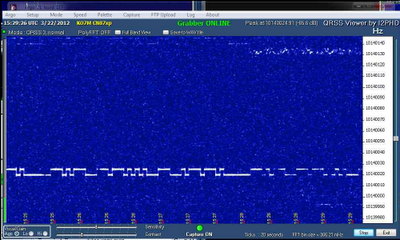
I have put up a QRSS grabber in Redmond, WA for those QRSS fans out there that would like to see how they are doing getting into this part of the world.
The grabber will be online most of the time except when I decide to grab the 7200 for other purposes. It can be found at http://www.qsl.net/k/ko7m//grabber/. My pal Eldon has his grabber back online now as well. He is about 35 miles north of my location.
Showing posts with label QRSS. Show all posts
Thursday, March 22, 2012
Thursday, February 2, 2012
Propeller WSPR Beacon Power Amp Results
This morning I finished up my beacon power amp by putting in the low pass filter. I had a bit of a struggle with that however, as I had no capacitors that would work for the 5 pole filter in hand. I ended up with some rather significant changes in values in my substituted capacitors. The filter modeling still showed that I would barely meet a 40 dB supression of the harmonics, so some additional work is needed here before I can call this complete.
The final breadboard looks like this:
The Propeller Beacon with it's outboard low pass filter is putting in a nice clean signal to the input.
Checking the output with the spectrum analyzer, I can see that the harmonics are 40 dB down or better (but just barely).
So, hooking this up to the matched antenna and measuring the power output, I got found that I was putting out a solid 2 watts.
This is pushing things quite a bit and the transistor finals were getting quite warm. I backed off the bias on the driver until the power dropped to about 500-600 mW.
It seems happy at this level and the entire amplifier draws about 160 mA at this setting at 12 V.
So, we let a WSPR transmission happen on the next even minute and were immediately rewarded:
So, I am quite pleased with the initial results. I have (subsequently) changed my power setting reported to correctly reflect my new power level. More work to be done to clean up the harmonic supression to have some more margin. I am seeing some fluctuation in SWR that appears to be related to the effects of harmonics, so more work to do, but for now we are on the air at around 27 dBm.
The final breadboard looks like this:
The Propeller Beacon with it's outboard low pass filter is putting in a nice clean signal to the input.
Checking the output with the spectrum analyzer, I can see that the harmonics are 40 dB down or better (but just barely).
So, hooking this up to the matched antenna and measuring the power output, I got found that I was putting out a solid 2 watts.
This is pushing things quite a bit and the transistor finals were getting quite warm. I backed off the bias on the driver until the power dropped to about 500-600 mW.
It seems happy at this level and the entire amplifier draws about 160 mA at this setting at 12 V.
So, we let a WSPR transmission happen on the next even minute and were immediately rewarded:
So, I am quite pleased with the initial results. I have (subsequently) changed my power setting reported to correctly reflect my new power level. More work to be done to clean up the harmonic supression to have some more margin. I am seeing some fluctuation in SWR that appears to be related to the effects of harmonics, so more work to do, but for now we are on the air at around 27 dBm.
Wednesday, February 1, 2012
Update on Power Amplifier
Um... Ok... I lied... It is just plain ugly construction...
But, hey... We are trying to prove a concept, right? :) Well, time to see if I can let the magic smoke out of it... I have not built the output 5 pole filter yet, there will be time for that once things check out a bit.
I hooked up the 12V current limited supply and with the current limit just above the minimum current shutoff, slowly turned up the voltage to 12 VDC and there was no current draw. So far so good.
Next I hooked up a dummy load, scope to the output and my beacon on the input. Here is the lashup:
I had set the bias pot all the way down. With the beacon supplying about 1.2 V of signal to the input, I slowly adjusted the bias until the finals kicked in. There is a noticeable threshold effect from the unbiased output stage, but it kicked in at about 2.1 VDC of bias. I ran it up to around 2.8 VDC and the current limiter kicked in (remember it is set to turn off at a very low current value. For the moment I have bias set a 2.75 VDC and am seeing this on the output. Remember there are no low pass filters yet in place and the bias is just rough set. Pretty ratty looking, rather terrible really but about 5.5 V P-P into 50 ohms. There is no skipping a low pass filter on this device.
This is would represent about 75 mW, given the unfiltered output. There is quite a bit of energy going to harmonics with this waveform and we really have not explored the bias setting or allowed the entire amp to consume more than about 6 mA, so the finals are not even getting slightly warm yet. More testing to come.
So, it's time to build a low pass filter and do some more adjustments and performance tuning.
Note to self: Gorilla glue sucks... Don't use it for breadboarding circuits...
But, hey... We are trying to prove a concept, right? :) Well, time to see if I can let the magic smoke out of it... I have not built the output 5 pole filter yet, there will be time for that once things check out a bit.
I hooked up the 12V current limited supply and with the current limit just above the minimum current shutoff, slowly turned up the voltage to 12 VDC and there was no current draw. So far so good.
Next I hooked up a dummy load, scope to the output and my beacon on the input. Here is the lashup:
I had set the bias pot all the way down. With the beacon supplying about 1.2 V of signal to the input, I slowly adjusted the bias until the finals kicked in. There is a noticeable threshold effect from the unbiased output stage, but it kicked in at about 2.1 VDC of bias. I ran it up to around 2.8 VDC and the current limiter kicked in (remember it is set to turn off at a very low current value. For the moment I have bias set a 2.75 VDC and am seeing this on the output. Remember there are no low pass filters yet in place and the bias is just rough set. Pretty ratty looking, rather terrible really but about 5.5 V P-P into 50 ohms. There is no skipping a low pass filter on this device.
This is would represent about 75 mW, given the unfiltered output. There is quite a bit of energy going to harmonics with this waveform and we really have not explored the bias setting or allowed the entire amp to consume more than about 6 mA, so the finals are not even getting slightly warm yet. More testing to come.
So, it's time to build a low pass filter and do some more adjustments and performance tuning.
Note to self: Gorilla glue sucks... Don't use it for breadboarding circuits...
More power for Propeller Beacon
While I have enjoyed the few WSPR spots I have received:
I have received no QRSS or Opera spots at all. There are times when I think (wishfully) that I see my 5 mW QRSS trace on remote grabbers, I have not been able to definatively say that I see my signal. So, I think it is time to bring the power level up to a more respectable 10-20 dBm.
I have been scouting around for some interesting designs that I might actually have parts for. I have a boatload of 2N7000 devices, so my focus has been in this area. After some searching I have decided to try out the following design taken from the Wee Willy DSB rig described over on the "popcorn" site.
Don't know how well this is going to work out, but you never know until you try it, so off I go. I am going to build this dead-bug style with a little Manhatten style thrown in for good measure. I even went out and picked up a fresh super-glue tube. Unfortunately, I got it home only to discover that it is a solid mass. Rats...
So, I had to resort to Gorilla glue, unfortunately. It will elongate my building time a bit as it takes a while to dry. But we are building again after a long hiatus.
So, I will post the build progress and performance results as I go. Should be fun!
I have received no QRSS or Opera spots at all. There are times when I think (wishfully) that I see my 5 mW QRSS trace on remote grabbers, I have not been able to definatively say that I see my signal. So, I think it is time to bring the power level up to a more respectable 10-20 dBm.
I have been scouting around for some interesting designs that I might actually have parts for. I have a boatload of 2N7000 devices, so my focus has been in this area. After some searching I have decided to try out the following design taken from the Wee Willy DSB rig described over on the "popcorn" site.
Don't know how well this is going to work out, but you never know until you try it, so off I go. I am going to build this dead-bug style with a little Manhatten style thrown in for good measure. I even went out and picked up a fresh super-glue tube. Unfortunately, I got it home only to discover that it is a solid mass. Rats...
So, I had to resort to Gorilla glue, unfortunately. It will elongate my building time a bit as it takes a while to dry. But we are building again after a long hiatus.
So, I will post the build progress and performance results as I go. Should be fun!
Tuesday, January 31, 2012
Propeller Beacon Update
I have taken the baseline beacons that I have created for QRSS, WSPR and Opera and put them together into a single beacon.
WSPR is on a 10 minute cycle (TX Percent = 20%). QRSS follows and just sends my call sign. Opera then follows and the remainder of the 10 minute cycle is idle. WSPR goes first because it has the even minute starting time requirement.
I have created each of the beacons as separate objects that the main beacon code can instantiate and call. The main beacon code looks like this:
CON
_CLKMODE = XTAL1 + PLL16X
_XINFREQ = 5_000_000
WMin = 381 'WAITCNT-expression-overhead Minimum
OBJ
WSPR : "ko7mBeaconWSPR"
QRSS : "ko7mBeaconQRSS"
Opera : "ko7mBeaconOpera"
Clock : "ko7mClock"
Freq : "Synth"
VAR
LONG Sync
PUB Main
doInitialize
repeat
WSPR.doBeacon ' 2 minutes (110.6 seconds) for WSPR
delay(10000) ' Delay 10 seconds before doing QRSS
QRSS.doBeacon ' QRSS is about 3 minutes
delay(10000) ' Delay 10 seconds before doing Opera
Opera.doBeacon ' Opera is about 3 minutes
repeat while Clock.getSeconds // Sync
delay(100)
PUB doInitialize
Sync := 10 * 60 ' Beacons cycle every 10 minutes
Clock.Start
PUB delay(Duration)
waitcnt(((clkfreq / 1_000 * Duration - 3932) #> WMin) + cnt)
The beacon is up and running as of now. I would love to have any reports if anyone is able to spot any of my three beacons.
WSPR is on a 10 minute cycle (TX Percent = 20%). QRSS follows and just sends my call sign. Opera then follows and the remainder of the 10 minute cycle is idle. WSPR goes first because it has the even minute starting time requirement.
I have created each of the beacons as separate objects that the main beacon code can instantiate and call. The main beacon code looks like this:
CON
_CLKMODE = XTAL1 + PLL16X
_XINFREQ = 5_000_000
WMin = 381 'WAITCNT-expression-overhead Minimum
OBJ
WSPR : "ko7mBeaconWSPR"
QRSS : "ko7mBeaconQRSS"
Opera : "ko7mBeaconOpera"
Clock : "ko7mClock"
Freq : "Synth"
VAR
LONG Sync
PUB Main
doInitialize
repeat
WSPR.doBeacon ' 2 minutes (110.6 seconds) for WSPR
delay(10000) ' Delay 10 seconds before doing QRSS
QRSS.doBeacon ' QRSS is about 3 minutes
delay(10000) ' Delay 10 seconds before doing Opera
Opera.doBeacon ' Opera is about 3 minutes
repeat while Clock.getSeconds // Sync
delay(100)
PUB doInitialize
Sync := 10 * 60 ' Beacons cycle every 10 minutes
Clock.Start
PUB delay(Duration)
waitcnt(((clkfreq / 1_000 * Duration - 3932) #> WMin) + cnt)
The beacon is up and running as of now. I would love to have any reports if anyone is able to spot any of my three beacons.
Wednesday, January 18, 2012
Beacon Power Output
My Propeller beacon is now on the air on 30 metres. Currently running QRSS near the bottom of the band (10.140.000) sending "KO7M CN87" in 5 hz FSK. Would love to have any reception reports. Currently running around 7 mW into a fence-mounted vertical. SWR is 1:1 fortunately. :) I will from time-to-time (on a whim) reconfigure it as I am now working on getting the WSPR beacon code to be autonomous which involves figuring out how to do the strict WSPR timing of transmissions.
More Propeller Frequency Stability
After wrapping the propeller board in foam, from a cold start, after about 30 minutes the frequency stabilized at about 30 Hz lower than the cold start value.
So, it appears that my chasing of this error correction value has been a bit of a boondoggle as I had not attended to the temperature stability of the device. (Doh!) I should be able to zero in on my ErrorOffset value and be able to let it be, or so I hope.
Tuesday, January 17, 2012
Propeller frequency stability
This evening, I have been experimenting a bit with my Propeller device. I have a small script that turns on the RF synthesizer at 10_140_000 mHz for 30 seconds, off for 10 seconds etc. I use it for calibration of the frequency of the board in use as different Propeller boards will have different amounts of error in frequency generation. The script looks like this:
CON
_CLKMODE = XTAL1 + PLL16X
_XINFREQ = 5_000_000
CLK_FREQ = ((_CLKMODE-XTAL1)>>6)*_XINFREQ
MS_001 = CLK_FREQ / 1_000
RFPin = 27
TxFreq = 10_140_000
ErrorOffset = -467
Frequency = TxFreq + ErrorOffset
VAR
OBJ
Freq : "Synth"
PUB Main
repeat
sendTone(0)
delay(30000)
noTone
delay(10000)
PUB delay(ms) | t
t := cnt - 1088 ' 1088 is published time for overhead
repeat ms
waitcnt(t += MS_001)
PUB sendTone(tone)
Freq.Synth("A",RFPin, Frequency + tone)
PUB noTone
Freq.Synth("A",RFPin, 0)
This simple little script I find to be very useful when I need to generate a signal at some frequency. The on/off modulation of the signal allows me to find it more easily on uncalibrated receivers.
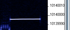
Viewing the output from a local receiver using Argo we find this waveform. As you can see, my board has approximately -467 Hz of error which is corrected for in this script. Nevertheless, as the board changes temperature, it does drift a bit. As can be seen below I have drifted a hertz or two lower since calibration of the board was last done.
I begin to wonder however why this ErrorOffset value seems to change when using the same board, just a different application. For example my Hellscrieber code appears to transmit about 3 Hz lower with the same ErrorOffset value. I added a 30 second carrier at the beginning of the code to see exactly what frequency it is on before launching into the transmission of FeldHell codes. With the transmit frequency set to 10_139_980 and the same -467 ErrorOffset value, the following is observed:
I am clearly 5-6 Hz low. The frequency is also different than in the previous example, so that may be related. I think however that it may just be the drift of the device. Going back to the Tune application, which should be a hertz or two low at 10_140_000, we see the following:
Hmmm... So it appears that I am just chasing a temperature drift of the Propeller board over time. Adding some thermal stabilization to it would probably help. I will wrap it up in some foam and let it run for a while and see if the frequency stabilizes.
Here is a cold start image of my QRSS signal. Out of the box, it seems that there is a significant drift:
And a few minutes later we can see it has drifted over 20 Hz:
I will let it run and see where it stabilizes.
CON
_CLKMODE = XTAL1 + PLL16X
_XINFREQ = 5_000_000
CLK_FREQ = ((_CLKMODE-XTAL1)>>6)*_XINFREQ
MS_001 = CLK_FREQ / 1_000
RFPin = 27
TxFreq = 10_140_000
ErrorOffset = -467
Frequency = TxFreq + ErrorOffset
VAR
OBJ
Freq : "Synth"
PUB Main
repeat
sendTone(0)
delay(30000)
noTone
delay(10000)
PUB delay(ms) | t
t := cnt - 1088 ' 1088 is published time for overhead
repeat ms
waitcnt(t += MS_001)
PUB sendTone(tone)
Freq.Synth("A",RFPin, Frequency + tone)
PUB noTone
Freq.Synth("A",RFPin, 0)
This simple little script I find to be very useful when I need to generate a signal at some frequency. The on/off modulation of the signal allows me to find it more easily on uncalibrated receivers.
Viewing the output from a local receiver using Argo we find this waveform. As you can see, my board has approximately -467 Hz of error which is corrected for in this script. Nevertheless, as the board changes temperature, it does drift a bit. As can be seen below I have drifted a hertz or two lower since calibration of the board was last done.
I begin to wonder however why this ErrorOffset value seems to change when using the same board, just a different application. For example my Hellscrieber code appears to transmit about 3 Hz lower with the same ErrorOffset value. I added a 30 second carrier at the beginning of the code to see exactly what frequency it is on before launching into the transmission of FeldHell codes. With the transmit frequency set to 10_139_980 and the same -467 ErrorOffset value, the following is observed:
I am clearly 5-6 Hz low. The frequency is also different than in the previous example, so that may be related. I think however that it may just be the drift of the device. Going back to the Tune application, which should be a hertz or two low at 10_140_000, we see the following:
Hmmm... So it appears that I am just chasing a temperature drift of the Propeller board over time. Adding some thermal stabilization to it would probably help. I will wrap it up in some foam and let it run for a while and see if the frequency stabilizes.
Here is a cold start image of my QRSS signal. Out of the box, it seems that there is a significant drift:
And a few minutes later we can see it has drifted over 20 Hz:
I will let it run and see where it stabilizes.
Monday, January 16, 2012
Hellschreiber QRSS using Propeller
Last evening, I shared the experience of creating a FeldHell-like QRSS beacon. The bulk of the effort was in creating an acceptable font. The Propeller chip has a rather nice font already in ROM but it is more suited for TV video output than for QRSS due to its 16x32 size. I felt that this was too much bandwidth to occupy for a single signal in the QRSS band.
I created the font definition in a text editor and decided to try a 5x7 font initially. With this format, each character is 5 bytes (one byte for each column of the font character). For example, the letter "A" is represented thus:
XXX
X X
X X
XXXXX
X X
X X
X X
Each colum of the character in the 5x7 grid is encoded as a byte where the "X" character above is encoded as a set bit and the lack of an "X" is encoded as a 0. So to create this, I defined all my characters (0..9, A..Z) as shown above in a text file. I then imported the text file into a spreadsheet and rotated the rows and columns 90 degrees using the spreadsheet "Transpose" function. This had the effect of laying all the characters down on their sides, thus:
XXXXXX
X X
X X
X X
XXXXXX
I then exported the file back to a text file for further processing. You have to now imagine each of the font characters lying on their sides like the example above, occupying five very long lines of my text file. I then globally replaced all the space characters (there is a space in each 5x7 grid anyplace there is no "X") with a "0" character and replaced the "X" characters with "1". For the "A" character above, this resulted in:
0111111
1001000
1001000
1001000
0111111
I then turned this mess into a valid DAT block containing binary byte values like so:
DAT
' FeldHell font definitions
' A B etc
Col5 BYTE %0111111, %xxxxxxx, ...
Col4 BYTE %1001000, %xxxxxxx, ...
Col3 BYTE %1001000, %xxxxxxx, ...
Col2 BYTE %1001000, %xxxxxxx, ...
Col1 BYTE %0111111, %xxxxxxx, ...
Now I can index into this table and obtain the column data I need for each character. So now in the main loop, I can call this procedure to process the beacon text:
PUB doFeldHellBeacon
' Send Feld Hell beacon text
sendFeldHellString(string("KO7M CN87xp"))
PUB sendFeldHellString(strMsg)
repeat STRSIZE(strMsg)
sendFeldHellChar(BYTE[strMsg++])
The code to send each character is a quick hack, so don't beat me up too much. I am still playing around with the timing to make it look nice. Each character of the message text is looked up in the DAT table above to obtain the byte containing each of the 5 column definitions. The character is sent from bottom left (least significant bit of Col1) to the top of the column and then proceeding with the next column until all five columns have been sent. I test the least significant bit of each byte of column data and send a tone if it is set and send nothing if unset. Right shift to get the next bit and continue for all 7 bits.
PUB sendFeldHellChar(ch) | i, j, iCol, columnData, Time
Time := 300
' set up column index to default to space character
iCol := -1
case ch
"a".."z": iCol := ch - "a" + 10
"A".."Z": iCol := ch - "A" + 10
"0".."9": iCol := ch - "0"
if iCol < 0
delay(Time*12) ' Handle the space character specially
else
repeat i from 4 to 0 ' 5 columns in reverse order
columnData := Col5[iCol+(i*36)] ' get the current column data
repeat j from 0 to 6
if columnData & 1 ' If the font bit is set, send a tone
sendTone(j*2)
else
noTone
columnData >>= 1 ' Right shift font data to get next bit
delay(Time) ' Give a little space between columns
noTone
delay(Time*6) ' Give a little more space between letters
So, that is it... Simple, eh? Since the font definition is five really long lines of text, I am not going to post the entire program here. If you would like to have a copy of it however, I will be happy to email it to you if you will drop me a comment to this post on the blog.
I will be creating "a".."z" characters in the font and some punctuation, but have no plans to create any characters beyond what would be in a typical QRSS message. I am using Eldon's 10 minute QRSS sync algorithm for stacked grabbers. See his article here.
Here is what it looks like on the air:
I created the font definition in a text editor and decided to try a 5x7 font initially. With this format, each character is 5 bytes (one byte for each column of the font character). For example, the letter "A" is represented thus:
XXX
X X
X X
XXXXX
X X
X X
X X
Each colum of the character in the 5x7 grid is encoded as a byte where the "X" character above is encoded as a set bit and the lack of an "X" is encoded as a 0. So to create this, I defined all my characters (0..9, A..Z) as shown above in a text file. I then imported the text file into a spreadsheet and rotated the rows and columns 90 degrees using the spreadsheet "Transpose" function. This had the effect of laying all the characters down on their sides, thus:
XXXXXX
X X
X X
X X
XXXXXX
I then exported the file back to a text file for further processing. You have to now imagine each of the font characters lying on their sides like the example above, occupying five very long lines of my text file. I then globally replaced all the space characters (there is a space in each 5x7 grid anyplace there is no "X") with a "0" character and replaced the "X" characters with "1". For the "A" character above, this resulted in:
0111111
1001000
1001000
1001000
0111111
I then turned this mess into a valid DAT block containing binary byte values like so:
DAT
' FeldHell font definitions
' A B etc
Col5 BYTE %0111111, %xxxxxxx, ...
Col4 BYTE %1001000, %xxxxxxx, ...
Col3 BYTE %1001000, %xxxxxxx, ...
Col2 BYTE %1001000, %xxxxxxx, ...
Col1 BYTE %0111111, %xxxxxxx, ...
Now I can index into this table and obtain the column data I need for each character. So now in the main loop, I can call this procedure to process the beacon text:
PUB doFeldHellBeacon
' Send Feld Hell beacon text
sendFeldHellString(string("KO7M CN87xp"))
PUB sendFeldHellString(strMsg)
repeat STRSIZE(strMsg)
sendFeldHellChar(BYTE[strMsg++])
The code to send each character is a quick hack, so don't beat me up too much. I am still playing around with the timing to make it look nice. Each character of the message text is looked up in the DAT table above to obtain the byte containing each of the 5 column definitions. The character is sent from bottom left (least significant bit of Col1) to the top of the column and then proceeding with the next column until all five columns have been sent. I test the least significant bit of each byte of column data and send a tone if it is set and send nothing if unset. Right shift to get the next bit and continue for all 7 bits.
PUB sendFeldHellChar(ch) | i, j, iCol, columnData, Time
Time := 300
' set up column index to default to space character
iCol := -1
case ch
"a".."z": iCol := ch - "a" + 10
"A".."Z": iCol := ch - "A" + 10
"0".."9": iCol := ch - "0"
if iCol < 0
delay(Time*12) ' Handle the space character specially
else
repeat i from 4 to 0 ' 5 columns in reverse order
columnData := Col5[iCol+(i*36)] ' get the current column data
repeat j from 0 to 6
if columnData & 1 ' If the font bit is set, send a tone
sendTone(j*2)
else
noTone
columnData >>= 1 ' Right shift font data to get next bit
delay(Time) ' Give a little space between columns
noTone
delay(Time*6) ' Give a little more space between letters
So, that is it... Simple, eh? Since the font definition is five really long lines of text, I am not going to post the entire program here. If you would like to have a copy of it however, I will be happy to email it to you if you will drop me a comment to this post on the blog.
I will be creating "a".."z" characters in the font and some punctuation, but have no plans to create any characters beyond what would be in a typical QRSS message. I am using Eldon's 10 minute QRSS sync algorithm for stacked grabbers. See his article here.
Here is what it looks like on the air:
More Propeller Madness
Well, my old pal Eldon has really done it now... So much for sleep it seems with new toys to play with...
I decided to implement FeldHell mode on my Propeller based QRSS/WSPR/Opera/CW beacon. It was a bit fun figuring out the timing and the font, but here is a sample:
It is a simple 5x7 font and I draw each character from the lower left to the upper right resulting in the slight forward slant of the characters. Right now I have only defined upper case characters and numerics in the font.
I will post the complete code after I have gotten some sleep... :)
I decided to implement FeldHell mode on my Propeller based QRSS/WSPR/Opera/CW beacon. It was a bit fun figuring out the timing and the font, but here is a sample:
It is a simple 5x7 font and I draw each character from the lower left to the upper right resulting in the slight forward slant of the characters. Right now I have only defined upper case characters and numerics in the font.
I will post the complete code after I have gotten some sleep... :)
Sunday, January 15, 2012
Propeller Opera beacon up and running tonight
Today I have built a low-pass filter for my Propeller beacon on 30 metres. The spectrum analyzer shows the second and subsequent harmonics more than 45 db down, so I have put it on the air tonight. I am beaconing every 15 minutes using Opera mode running only 5.6 mW currently.
Here is the current setup. As you can see Eldon and I have shared the low pass filter design that he created with the aide of a design program.
I am eager, but not too hopeful that this little pennywhistle signal will be picked up somewhere this evening. We shall see. Thanks Eldon for sharing your design and the components necessary to build the low pass filter!
Here is the current setup. As you can see Eldon and I have shared the low pass filter design that he created with the aide of a design program.
I am eager, but not too hopeful that this little pennywhistle signal will be picked up somewhere this evening. We shall see. Thanks Eldon for sharing your design and the components necessary to build the low pass filter!
Saturday, January 14, 2012
First Opera reception
Well, thanks to my buddy Eldon WA0UWH, I have been drug kicking and screaming into the world of Opera QRSS and the Propeller processor.
Stealing judiciously from the work of others, I have put together a beacon using the propeller processor and have Opera v1.1.0 beta up and running. This morning I heard myself first (imagine that...) and then N7VVX down in Utah. So, it seems another diversion is born... Thanks Eldon... :|
Before I can really put the propeller on the air, I will need to build a low pass filter for it as the output is a square wave. The reception of my own call (KO7M) is without any antenna on the propeller board. My idea for my low pass filter board is to have a set of switchable (via software) low pass filters on a single board that should be useful for this and my Arduino WSPR beacon.
Stealing judiciously from the work of others, I have put together a beacon using the propeller processor and have Opera v1.1.0 beta up and running. This morning I heard myself first (imagine that...) and then N7VVX down in Utah. So, it seems another diversion is born... Thanks Eldon... :|
Before I can really put the propeller on the air, I will need to build a low pass filter for it as the output is a square wave. The reception of my own call (KO7M) is without any antenna on the propeller board. My idea for my low pass filter board is to have a set of switchable (via software) low pass filters on a single board that should be useful for this and my Arduino WSPR beacon.
Monday, November 14, 2011
LCD Performance and UI decisions in the beacon project
The beacon project is back on the front burner. Frankly, one of the reasons that it has been stalled so long is because of the lousy UI performance. The rotary encoder triggers an interrupt so I never lose control turns. However, the display updates are very laggy and the amount of lag varies considerably. I *HATE* laggy UIs and until now have not looked into why. Frankly the I2C LiquidCrystal library was apparently a hasty adaptation of the original LCD library without regard to performance. It was taking more than a dozen I2C commands for a single character to be updated, let alone the additional ones for cursor positioning and the like. Bogus. All bits are written simultaneously now and the lagginess is completely gone. Sweet! Many thanks to Kevin who pointed out the great work by falconfour in a comment to one of my previous posts. Nice to be back on track and re-energized to complete this project.
I spent a lot of time talking to my pal Eldon about UI decisions. I will be making some changes to the value setting library for alpha-numeric fields to see if the new paradigm works a little cleaner for non-numeric fields.
Another concept that we kicked around was the effect of TX percent on multi-band operation for WSPR. Since WSPR frequencies have been cleanly defined for all bands, I am considering having TX percent of 100% mean the beacon will cycle through all bands on each two minute window. A setup UI would be created to allow enable/disable of each of the bands. See my previous post for a list of bands supported by this beacon (all up to and including 6 metres). So, if you truely wanted to send 100% of the time on one band, you would have to disable all other bands as well as setting TX percent to 100%. Otherwise, the beacon would sequence through the list of enabled bands every two minute window. I am interested in feedback on this idea. I think it makes sense to enable this multi-band mode only on TX percent = 100% as otherwise, i would have to completely rethink the meaning of TX percent when multiple bands are enabled.
Also regarding multi-band operation, I plan to make some concession for external low-pass filter selection based on the currently selected band or frequency. Interested in feedback on what this might look like. Some ideas:
Eldon and I also revisited the whole topic of what frequency to display on the LCD when in WSPR mode. Most folks that use the great software by Joe Taylor are used to setting the rig display (on 30 metres for example) to 10.138700 MHz and generating tones in the 1400-1600 hz range to feed into your SSB transmitter. The actual transmit frequency can be set by double clicking in the "waterfall" display or by typing it in to the "Tx:" frequency edit box. One idea kicked around was to only display the WSPR band (30 metres, 20 metres, etc) and an offset from the start of the WSPR band. The offset is only 200 hertz total. This sort of makes sense to me, but I have an uneasyness when I don't know precisely what frequency I am transmitting on. Joe Taylor's software shows the exact transmit frequency. For example, if you clicked in the middle of the 30 metre band, it will show 14.140200 in the "Tx:" frequency box. What is not clear to me is precisely what that frequency means since WSPR signals are composed of four separate tone frequencies that are separated by 1.4648 Hz. In the absence of clarity from Joe's documentation, I have chosen to define the transmit frequency like this:
Each symbol is 1.4648 Hz apart and the displayed transmit frequency is mid-way between symbols 1 and 2. Band edge operations need to take this into account if you wish to stay within the defined WSPR frequency range with the entire 6 Hz spectrum occupied by the complete WSPR signal. Anyone have further thoughts or comments on this?
Anyway, it is nice to be back on track and making progress on my beacon again.
I spent a lot of time talking to my pal Eldon about UI decisions. I will be making some changes to the value setting library for alpha-numeric fields to see if the new paradigm works a little cleaner for non-numeric fields.
Another concept that we kicked around was the effect of TX percent on multi-band operation for WSPR. Since WSPR frequencies have been cleanly defined for all bands, I am considering having TX percent of 100% mean the beacon will cycle through all bands on each two minute window. A setup UI would be created to allow enable/disable of each of the bands. See my previous post for a list of bands supported by this beacon (all up to and including 6 metres). So, if you truely wanted to send 100% of the time on one band, you would have to disable all other bands as well as setting TX percent to 100%. Otherwise, the beacon would sequence through the list of enabled bands every two minute window. I am interested in feedback on this idea. I think it makes sense to enable this multi-band mode only on TX percent = 100% as otherwise, i would have to completely rethink the meaning of TX percent when multiple bands are enabled.
Also regarding multi-band operation, I plan to make some concession for external low-pass filter selection based on the currently selected band or frequency. Interested in feedback on what this might look like. Some ideas:
- Provide the frequency to an external function that takes care of the magic itself and leave the details up to the implementer.
- Provide an enable bit (or a counter that is decoded by external hardware) that can be used trigger external relays to select an appropriate low pass filter which is set by one of the following:
- The function described in #1 above as implemented by someone else.
- Providing a set of configurable cutoff frequencies for the various external low-pass filters and automatically selecting one as appropriate based on frequency.
- Define one filter per WSPR band and select based on frequency. This is simple, but may be somewhat inappropriate as for example it makes little sense to have separate low pass filters for both 12 and 10 metres where one would suffice.
Eldon and I also revisited the whole topic of what frequency to display on the LCD when in WSPR mode. Most folks that use the great software by Joe Taylor are used to setting the rig display (on 30 metres for example) to 10.138700 MHz and generating tones in the 1400-1600 hz range to feed into your SSB transmitter. The actual transmit frequency can be set by double clicking in the "waterfall" display or by typing it in to the "Tx:" frequency edit box. One idea kicked around was to only display the WSPR band (30 metres, 20 metres, etc) and an offset from the start of the WSPR band. The offset is only 200 hertz total. This sort of makes sense to me, but I have an uneasyness when I don't know precisely what frequency I am transmitting on. Joe Taylor's software shows the exact transmit frequency. For example, if you clicked in the middle of the 30 metre band, it will show 14.140200 in the "Tx:" frequency box. What is not clear to me is precisely what that frequency means since WSPR signals are composed of four separate tone frequencies that are separated by 1.4648 Hz. In the absence of clarity from Joe's documentation, I have chosen to define the transmit frequency like this:
Each symbol is 1.4648 Hz apart and the displayed transmit frequency is mid-way between symbols 1 and 2. Band edge operations need to take this into account if you wish to stay within the defined WSPR frequency range with the entire 6 Hz spectrum occupied by the complete WSPR signal. Anyone have further thoughts or comments on this?
Anyway, it is nice to be back on track and making progress on my beacon again.
Sunday, August 28, 2011
Back to working on the beacon project
I know it has been forever since I started the Arduino beacon project and while the functionality is 90% or better complete, the project has been on the shelf for a very long time. Between family illness, work issues and the like, ham radio has taken a bit of a holiday.
Today I drug out the beacon hardware and spent some time reviewing the software. I made sure I could still build the code and flash the device with the image. All is well in that department. I spent some time tidying things up a bit in the code and removing some edge case failures.
I have reduced the functionality of the software to three modes:
1. Signal Generator - General purpose, turn the dial, set the frequency mode.
2. WSPR beacon
3. QRSS beacon
There is also a real-time clock setting mode, but that is more of a utility.
The WSPR beacon has preprogrammed all defined WSPR frequencies from 500 kHz to 50 mHz. A single button push will cycle through all of the WSPR frequencies and sets the beacon to the centre of the band. From there, the rotary dial will allow adjustment down to 1 Hz.
The QRSS beacon transmits on whatever frequency is set on the dial. The beacon continually transmits until the operating mode is changed.
There are a few things to do yet to finish off version 1 of this project.
1. WSPR mode needs to allow adjustment of the TX percent value as well as the call sign and power level. Currently it requires recompiling the code to change these values. The TX percent value is not currently respected and the beacon currently transmits once and then enters IDLE mode until WSPR mode is reselected.
2. QRSS mode needs to allow changing the QRSS message without recompiling the code.
I think at this point the code could be declared V1 complete. A few lower priority changes might be the definition of V2.
1. The WSPR beacon should have a mode where it cycles through all 12 WSPR bands. The challenge here of course would be to create a 12 band antenna system from 500 kHz to 50 mHz.
2. Allowing finer control of the frequency with the rotary encoder. Currently the resolution is 1 Hz.
3. Automatic saving/restoring of all settable parameters in EEPROM.
I am going to try and get V1 completed by the time our QRP group meets this Wednesday. It will be a bit of a challenge, as I need to finish the packaging of the hardware, but will give it a go.
Today I drug out the beacon hardware and spent some time reviewing the software. I made sure I could still build the code and flash the device with the image. All is well in that department. I spent some time tidying things up a bit in the code and removing some edge case failures.
I have reduced the functionality of the software to three modes:
1. Signal Generator - General purpose, turn the dial, set the frequency mode.
2. WSPR beacon
3. QRSS beacon
There is also a real-time clock setting mode, but that is more of a utility.
The WSPR beacon has preprogrammed all defined WSPR frequencies from 500 kHz to 50 mHz. A single button push will cycle through all of the WSPR frequencies and sets the beacon to the centre of the band. From there, the rotary dial will allow adjustment down to 1 Hz.
The QRSS beacon transmits on whatever frequency is set on the dial. The beacon continually transmits until the operating mode is changed.
There are a few things to do yet to finish off version 1 of this project.
1. WSPR mode needs to allow adjustment of the TX percent value as well as the call sign and power level. Currently it requires recompiling the code to change these values. The TX percent value is not currently respected and the beacon currently transmits once and then enters IDLE mode until WSPR mode is reselected.
2. QRSS mode needs to allow changing the QRSS message without recompiling the code.
I think at this point the code could be declared V1 complete. A few lower priority changes might be the definition of V2.
1. The WSPR beacon should have a mode where it cycles through all 12 WSPR bands. The challenge here of course would be to create a 12 band antenna system from 500 kHz to 50 mHz.
2. Allowing finer control of the frequency with the rotary encoder. Currently the resolution is 1 Hz.
3. Automatic saving/restoring of all settable parameters in EEPROM.
I am going to try and get V1 completed by the time our QRP group meets this Wednesday. It will be a bit of a challenge, as I need to finish the packaging of the hardware, but will give it a go.
Saturday, April 2, 2011
Trying to spruce up the Arduino beacon project
The Arduino WSPR/QRSS beacon project has gotten to the point where it is time to try and get rid of some of the rats nest of the breadboard nature of the project so far. To that end, I have mounted the controls and display in a panel.
Next, I will be eliminating the breadboard and using a data logger shield for the Arduino. This shield has an SD card slot (which I do not need) as well as the same real-time-clock (RTC) I chose for my beacon project the DS1307. There is also some breadboard space available to mount a socket for the DDS-60 and any other associated discrete components I may need. This should tidy things up sufficiently to allow the software components to be finalized.
After the software bits are complete (as much as any software project ever is) I will be producing a PCB for the entire project.
So far, my project has grown a bit bloated as I have allowed myself to be sidetracked on numerous occasions by additional modes such as Feld Hell. I have added some test code to experiment in geneating Hellschrieber-like displays on a QRSS waterfall such as we have in Spectran or Argo. The resultant bloat has put the code size beyond the code size limit of the ATMega168. Since I am using an Arduino Uno with the 328 chip, this has not been a problem, but it does increase the expense of this project for others to duplicate or leverage the code. I will have to work on that and will try to get the code size as small as possible in the final versions. Things like my choice to do frequency calculations for the DDS using 64 bit integers has no doubt drug in the entire 64 bit math library whereas I only need one operation. Obviously many opportunities exist for further optimization.
Next, I will be eliminating the breadboard and using a data logger shield for the Arduino. This shield has an SD card slot (which I do not need) as well as the same real-time-clock (RTC) I chose for my beacon project the DS1307. There is also some breadboard space available to mount a socket for the DDS-60 and any other associated discrete components I may need. This should tidy things up sufficiently to allow the software components to be finalized.
After the software bits are complete (as much as any software project ever is) I will be producing a PCB for the entire project.
So far, my project has grown a bit bloated as I have allowed myself to be sidetracked on numerous occasions by additional modes such as Feld Hell. I have added some test code to experiment in geneating Hellschrieber-like displays on a QRSS waterfall such as we have in Spectran or Argo. The resultant bloat has put the code size beyond the code size limit of the ATMega168. Since I am using an Arduino Uno with the 328 chip, this has not been a problem, but it does increase the expense of this project for others to duplicate or leverage the code. I will have to work on that and will try to get the code size as small as possible in the final versions. Things like my choice to do frequency calculations for the DDS using 64 bit integers has no doubt drug in the entire 64 bit math library whereas I only need one operation. Obviously many opportunities exist for further optimization.
Sunday, March 27, 2011
QRSS/WSPR band befuddlement...
I know that on 30 metres, the dial frequency of 10.1387 plus
1300 Hz is the bottom of the QRSS band and plus 1400 Hz is the bottom of the WSPR
band. Is this true on all bands?
// middle of the 200 Hz WSPR band
502400 + 1500, // 500 KHz
1836600 + 1500, // 160 meters
3592600 + 1500, // 80 meters
5287200 + 1500, // 60 meters
7038600 + 1500, // 40 meters
10138700 + 1500, // 30 meters
14095600 + 1500, // 20 meters
18104600 + 1500, // 17 meters
21094600 + 1500, // 15 meters
24924600 + 1500, // 12 meters
28124600 + 1500, // 10 meters
50293000 + 1500 // 6 meters
};
WSPR500KHZ, WSPR160M, WSPR80M, WSPR60M,
WSPR40M, WSPR30M, WSPR20M, WSPR17M,
WSPR15M, WSPR12M, WSPR10M, WSPR6M
};
I see from the KnightQRSS blog that there appears to be a more scattered set of standard frequencies, though I am not certain I understand the decision making process and therefore don't have much confidence in this list:
* 137.6 - 137.8 kHz
* 1.8432
* 3.500, 3.575, 3.579, 3.5999
* 7.000, 7.0402, 7.0599
* 10.140
* 14.000, 14.0989, 14.31818
* 18.1089
* 21.000, 21.1489
* 24.9289
* 28.000, 28.188, 28.322
* 50.294,400-600
1300 Hz is the bottom of the QRSS band and plus 1400 Hz is the bottom of the WSPR
band. Is this true on all bands?
Here are the WSPR dial frequencies(USB) for everything below
60 MHz (limit of the DDS-60) according to http://www.wsprnet.org.
// WSPR standard frequencies
// Shown are the dial frequencies plus 1500 Hz to put in the // middle of the 200 Hz WSPR band
long rgWSPRFreq[] =
{502400 + 1500, // 500 KHz
1836600 + 1500, // 160 meters
3592600 + 1500, // 80 meters
5287200 + 1500, // 60 meters
7038600 + 1500, // 40 meters
10138700 + 1500, // 30 meters
14095600 + 1500, // 20 meters
18104600 + 1500, // 17 meters
21094600 + 1500, // 15 meters
24924600 + 1500, // 12 meters
28124600 + 1500, // 10 meters
50293000 + 1500 // 6 meters
};
enum
{WSPR500KHZ, WSPR160M, WSPR80M, WSPR60M,
WSPR40M, WSPR30M, WSPR20M, WSPR17M,
WSPR15M, WSPR12M, WSPR10M, WSPR6M
};
So, as I have defined them, I can set the DDS frequency to
the centre of the WSPR band with the array above. Are these WSPR/QRSS
band relationships consistent across all these bands as they are on 30M ?
the centre of the WSPR band with the array above. Are these WSPR/QRSS
band relationships consistent across all these bands as they are on 30M ?
I see from the KnightQRSS blog that there appears to be a more scattered set of standard frequencies, though I am not certain I understand the decision making process and therefore don't have much confidence in this list:
* 137.6 - 137.8 kHz
* 1.8432
* 3.500, 3.575, 3.579, 3.5999
* 7.000, 7.0402, 7.0599
* 10.140
* 14.000, 14.0989, 14.31818
* 18.1089
* 21.000, 21.1489
* 24.9289
* 28.000, 28.188, 28.322
* 50.294,400-600
On a side note, the 60 metre WSPR frequency surprises me as I thought only USB transmissions are available on 60 metres. Granted, most people typically inject tones into their SSB transceiver to transmit WSPR. What you get out when you do that however is FSK, so I am not so certain WSPR on 60 metres makes sense. What did I miss?
On a similar note, it is a bit "funny" to note the number of times I hear computer annunciation beeps and even an occasional VOIP phone call or MP3 tracks that makes its way into the SSB transceiver MIC input when in digital modes in "non-voice" portions of the ham bands, especially 30 metres...
Friday, March 18, 2011
GPIO Liberation
I have been endeavoring to liberate I/O pins on my Arduino project. To that end, I have moved to an I2C LCD interface. This is necessary to enable integration of an RTC (real-time clock) for WSPR timing. The new setup looks like this:
I have some concerns about the performance of the LCD driver so I may have to do some customization of the driver. The good news is that the beacon in operation is unlikely to have or need a display or rotary encoder as the set of operational frequencies will be fixed. Calibration of the DDS-60 can be accomplished with a test setup that includes a rotary encoder to set the clock and then disconnected for day-to-day operation.
So, hopefully I can get the RTC integration done soon and have a fully functional WSPR/QRSS beacon breadboard completed.
Many thanks to the good folks at Adafruit for the excellent work on the I2C LCD interface.
I have some concerns about the performance of the LCD driver so I may have to do some customization of the driver. The good news is that the beacon in operation is unlikely to have or need a display or rotary encoder as the set of operational frequencies will be fixed. Calibration of the DDS-60 can be accomplished with a test setup that includes a rotary encoder to set the clock and then disconnected for day-to-day operation.
So, hopefully I can get the RTC integration done soon and have a fully functional WSPR/QRSS beacon breadboard completed.
Many thanks to the good folks at Adafruit for the excellent work on the I2C LCD interface.
Thursday, March 3, 2011
QRSS with a DDS-60
I have been having fun messing around with an old DDS-60 board that I obtained some time ago. I have cabled it up to the Arduino. Here is the setup:
The DDS-60 is plugged into the Arduino breadboard. I have a small four line LCD display on a separate board below. The LCD is certainly not necessary for this project, but is nice to have.
Looking at the DDS-60 output on around 10 MHz, we see a nice clean signal.
A little more code and we have a simple QRSS beacon putting out about 1.4 V peak-to-peak signal into a 50 ohm load. Hooked up a simple Grundig G6 portable radio and cabled the audio out to the computer audio in. Using Spectran, we can see the 6 hertz FSK signal on 10.140 Mhz sending my call sign (KO7M).
The DDS-60 is plugged into the Arduino breadboard. I have a small four line LCD display on a separate board below. The LCD is certainly not necessary for this project, but is nice to have.
Looking at the DDS-60 output on around 10 MHz, we see a nice clean signal.
A little more code and we have a simple QRSS beacon putting out about 1.4 V peak-to-peak signal into a 50 ohm load. Hooked up a simple Grundig G6 portable radio and cabled the audio out to the computer audio in. Using Spectran, we can see the 6 hertz FSK signal on 10.140 Mhz sending my call sign (KO7M).
Subscribe to:
Posts (Atom)