Showing posts with label Arduino. Show all posts

Friday, April 13, 2018

New Due Case

I recently picked up a nice little laser-cut case for my Arduino Due.  This one is by GeauxRobot.  They did a nice job on it including making little T-shaped button plastics to make the reset and erase buttons available.

This one does a nice job of supporting the ends of the board.  All the I/O connectors are nice and flush with the top of the case so shields can be handled as well as the SPI and JTAG connectors being accessible.


Available on Amazon.  Be sure to use smile.amazon.com and support your favorite charity!

Saturday, April 29, 2017

Github updated

I have started to collect some useful tool source code for Arduino projects into a github repository.  Some of these projects have been published on this blog, but not all of them.  I will try to to maintain anything that I post here also on github for the convenience of those that find any of my examples useful.

You can find my Arduino github repository here.

Tuesday, April 18, 2017

Arduino IDE issues

Well, it has been a long time since I blogged anything so I thought I would jot down some notes about my experiences of late using recent builds of the Arduino IDE.

I have over the last couple of years been working almost exclusively on Linux workstations, specifically Ubuntu 16.04 LTS and later and my comments are based on my experience on that platform.  I have not yet attempted to reproduce any of this on Windows though I have no reason to doubt that experience would be the same.

In my case, I have loaded up Arduino 1.8.1 on Linux and I have several comments about the later builds and this one in particular.

  1. There has been a lot of work done on board management and library management and this from my perspective has been a very worthwhile addition to the system.  Having the ability to be notified when updates have been produced to the set of development boards supported as well as the libraries is a huge improvement over the older experience.  Trying to make sure you get a library zip file loaded in exactly the correct folder without destroying the base install is a welcome addition.
  2. In the same vein, there has been a bit of expansion on the scope of the 8 and 32 bit processors supported.  This support is bundled up in packages that can be individually installed to add or remove support.
  3. Someone finally addressed the issue of the serial monitor and serial plotter output windows having to be closed in order to recompile and upload the code.  Thank you!
There has also been a lot of work in turning on (by default) the various code optimization flags for the compilers and this has resulted in a lot of code space savings for my projects and I know for others.  It has not come without a price however and this is one of the things I want to highlight here.

One thing I have noticed is that the "link-time optimization" flags have been added to the default options during compile and link.  If you enable verbose output in file->preferences dialogue shown below, you can see these additional command line options during compilation.


While I am a fan of compact code, enabling these options on one of my projects has resulted in the code linker seg faulting during compilation.  I have not yet created a simple repro of the issue.  The following code illustrates the issue, but does not fail to compile, so my understanding of the issue is as yet incomplete.  I wrote this to try and reproduce the issue, but it fails to fail...


class data
{
public:
    int a;
    int b;
};

class classB
{
public:
    void doSomething(data *pData);        
};

class classA
{
public:
    void doit();
    
private:
    classB b;
    data d;   
};

void classB::doSomething(data *pData)
{
    pData->a = 1;
    pData->b = 2;
}

void classA::doit()
{
    b.doSomething(&d);
}


classA *pA;

void setup()
{
  pA = new classA();
}

void loop() 
{
    pA->doit();

}

The basic idea is that I have a class (classA) that has two other classes embedded in it (classB and data).  ClassB has a method (doSomething) that gets passed a pointer to class data which it attempts to use to access public variables in class data.  In my failure case, if I comment out the call to b.doSomething(&d) everything compiles fine.  If I uncomment it, the GNU linker Segment Faults and terminates.  The code above does not reproduce the symptoms.  In my project that does reproduce the problem, if I remove the -flto command line option to disable the link-time optimizer, there is no crash and with the option set it does crash.

There is a lot of discussion on the GNU tools blogs about this problem though my repo seems to be somewhat unique, so I have not been able to narrow the problem down further.  https://github.com/arduino/Arduino/issues/660

My temporary solution is to disable the link time optimizer and finish up the project.  Once it is complete, I will re-enable the option and see if the problem still reproduces.  I am not quite ready to publish this project, so I am going to wait until it is finished before reporting a bug back to GNU as I will have to publish the code to them to get it investigated.  Otherwise, I will build the tool myself from the source and debug it myself.  I just don't want to take the time at this moment with a side trip into debugging my toolchain.

Mostly, I wanted to publish this so that readers will be aware of it and if anyone has encountered the same problem, I would love to compare notes.

Saturday, November 28, 2015

PID Controllers

Wow...  Where to begin.  I have had the pleasure of trying to get my head around implementing a fairly simple controller for a linear fader control that is also motor controlled.

This is an Alps fader which is basically a linear 10K potentiometer that has a small DC motor mounted on the back.  It has a 100mm travel length and the fader control is touch sensitive.  Mouser and other suppliers have them, though I cannot recommend hobbyists buying them through these channels as they are quite expensive.  I have seen them on eBay and other auction sites at significant savings.


The motor is mounted along the axis of the linear fader making a very low profile solution.  The motor drives a toothed belt to move the fader to any position desired remotely.  The motor is a simple DC motor that can be driven by up to 10 VDC.


So, one could envision simply putting a voltage across the pot and connecting the wiper to an Arduino analogue input.  Moving the pot would report a digital number from 0-1023 at any given instant in time representing the voltage across the pot at the wiper and therefore, the relative position of the fader control.

 However, if we wanted to simply tell the fader to position itself to any of its 1024 positions it is capable of, we would basically need to turn the motor on and drive it in the correct direction while reading the pot position until it attains the correct value.  This would be an appropriate application for a PID controller.

To control a DC motor, it is most convenient to use an H-Bridge circuit.  As can be seen by the circuit diagram below, turning on Q1 and Q4 will drive the motor in one direction whilst turning on Q3 and Q2 will drive the motor in the opposite direction.  As an addition feature turning on Q1 and Q2 or Q3 and Q4 will short out the power supply and allow for stress testing your circuit protection implementation...


In reality, there are nice single chip H-Bridge solutions that not only allow for controlling the motor direction, but also allow for PWM control of motor speed.  Most suppliers of robotics components will have typical examples of these controllers as well as places like Adafruit and Sparkfun.

In my next posting, I will get into the details of the hookup and programming of the PID controller for this fader.  More to come...

Saturday, October 17, 2015

Fun with PIDs

PID?  What the heck is a PID?

According to Wikipedia, PID is a Proportional-Integral-Derivative controller (PID controller) which is any kind of control loop feedback mechanism.  These controllers find common usage in industrial control systems.

What a PID controller does is continuously calculate an error value as the difference between the measured value of something that is changing and the desired value.

Perhaps a simple example is in order.  Let's say you want to fill a pan of water at a specific temperature from the tap.  You have two sources of water, cold and hot.  You will need to control the mix of hot and cold water to obtain the desired temperature which you are going to measure with your finger.  So you start with a guess of the hot and cold water settings, measure the result and adjust the hot and cold flow until satisfied.  Making a change that is too big may result in overshooting or undershooting the desired temperature.

Lets call the water temperature sensed by your finger the "process variable" or PV.  The temperature that is desired, let's call the "set point" or SP.  The amount of change of the water flow mix of hot and cold, let's call the "control variable" or CV.  And lastly, the difference between the measured temperature and the desired temperature is the "error" or e.

The most obvious way to change the water flow is in proportion to the current error.  The bigger the error, the bigger the change.  A slightly more complex methodology might want consider the rate of change of the error adding more water flow control depending on how fast the error is approaching zero (a derivative action).  Another refinement might be to consider some historical accumulated error information to detect whether the temperature is settling out too low or too high and make the appropriate corrections (an integral action).  Another way to perform this integral action would be change the current water tap position in steps proportional the current error.

When making changes that result in overshoot or undershoot of the desired set point, continuing to do so will result in oscillations around the desired set point that either grow or decay with time.  If the oscillations decay, the system is stable.  If they grow, the system is unstable.  If they remain at a constant amplitude, the system is marginally stable.  The desired goal is a gradual convergence to the desired set point, so the controller may try to dampen future oscillations by tempering its adjustments by a process called reducing the loop gain.

When the controller starts from a stable state with no error (PV = SP), any changes made by the controller will be in response to changes in other inputs to the process that affect it.  These changes are known as disturbances.  An example of a disturbance in our simple system described above would be a change in the tap water temperature caused by an external event such as the water heater deciding to turn on its heating element.

In theory, a PID controller can be used to control any process which has a measurable output (PV), a known ideal for that output (SP) and an input to the process (CV) that will affect the PV.  So, as you can see PID controllers find uses in any problem domain that needs to regulate temperature, force, speed, pressure, flow rate, weight, position and just about any other variable for which a measurement exists.

So, now just a little bit about the theory of PID controllers.  The name as we have seen above comes from its three terms (Proportional, Integral and Derivative) which are summed to calculate the output of the controller.

The clasasic formula for the algorithm (from Wikipedia) is:


where:
   Kp - Proportional gain.  These first three are algorithm tuning parameters
   Ki  - Integral gain
   Kd - Derivative gain

   e   - Error = SP - PV

   t   - Time or instantaneous time (the present)
   T  - Variable of integration (takes values from time 0 to present time t)

What is desired is a controller that will smoothly make adjustments to the desired set point with minimal over-shoot and under-shoot.  Directly implementing this formula in code would lead to some simple solutions that would most likely suffer from a number of short-comings such as the following:

  • Sample Time - The formula requires recalculation at a regular interval since both integration and derivatives are a function of time.
  • Derivative Kick - Any time the set point (SP) is changed, the error is changed (SP-PV) and the derivative of this change is infinity.  In practice however, since the change in time is never zero, it ends up being a very big number which when fed into the calculation results is an undesirable spike in the output.
  • On the fly Tuning Changes - Changes in the three tuning parameters affect the integration of the error value over time.  Any change in Ki will be multiplied by the entire error sum that has been accumulating when we really only want it to affect the result going forward.
  • Reset Wind-up - Most controllers have some limit on operational ranges.  For example a water valve can only be set in the range of completely closed to completely open.  If the PID controller does not know about these ranges, it may calculate an output value that is out of range.  Over time when it tries to continue to add more water flow beyond maximum, only to have it clamped by the physical size of the pipe, the algorithm will continue to ask for more and more beyond the limit.  The result is that the output gets "wound up" way beyond the maximum limit.  Where the problem reveals itself is when the set point (SP) is dropped, the algorithm needs to wind back down again to the maximum before it will even affect the output.  This results in what looks like a lag in response of the controller to the new set point.
  • Switching the PID Controller on/off - This occurs when you validly decide that regardless of what the PID controller is doing, you want to override its decision for a period of time.  Now, when you stop overriding it's decision, you get a sudden, huge change in the output.  The controller keeps trying to adjust the output to get the desired result, but it doesn't see any change, so it adjusts the output a little more and so on.  It would be like externally overriding a volume control of a stereo system while trying to adjust the volume internally.  No change internally has any effect.  Then you switch off the external override and suddenly you have a huge volume change.
  • Initialization - While it is useful to be able to turn off the PID and set your own override, when you turn it back on, the PID jumps back to the last output value it had set resulting in another spike in the output.  These transitions need to be seamless.
  • Changing Direction - The PID algorithm may be used to drive a system that is either "direct acting" (an increase in the output causes an increase in the input) or "reverse acting" (an increase in the output causes a decrease in the input).  A refrigeration system for example is a reverse acting system as an increase in the cooling results in a decrease in temperature.  Changing the sign of Kp, Ki and Kd allows proper control of a reverse acting systems.
Rather than detail the solutions for all of these potential issues, let me refer you to a most excellent blog by Brett Beauregard detailing the improvements one-by-one starting with the most basic code example.  It is a great read and not one I could not improve upon.

There is a great PID implementation for the Arduino also available at the Arduino Playground which will be the subject of my next posting.

Sunday, September 20, 2015

Arduino Satellite/Sun Tracking

I have put together the recent bits and pieces of test code that I have been playing with to control my AZ/EL servo camera mount and an Arduino port of the old Plan13 code, originally written in Basic back in 1983 by James Miller G3RUH.  You can read about his efforts over on the AMSAT web site here.  Jim gives a great treatment of the math involved and example code in Basic.


A port of the code described on the page above has been made to the Arduino and I leveraged this code from the QRPTracker project web site.  With some simple changes, I have pulled together a simple satellite tracker to drive my AZ/EL camera mount.  It should be simple to scale this up to drive an actual satellite antenna array.


Here you can see the project pointing to the point in the sky where the ISS would be located at a point in time today.  I took the AMSAT Keplerian elements and processed the six passes today where the satellite was above the horizon at my location.  The code currently processes the entire 24 hour period in a day, and tracks in real time each of the passes.

The implementation of Plan13 is not particularly accurate due to the limited precision available in single precision floating point on the Arduino, but with the broad bandwidth of most amateur 144 and 440 MHz antennas, it is of little consequence even if the accuracy was only to the degree level.  In fact most low earth orbital satellites can be worked with a fixed elevation on a standard yagi, but the project has been interesting.  If there is interest, I will post my code, though most of it was gleaned from the efforts of others.

Beyond the code I have previously published, I have changed the mapping of the azimuth servo to be clockwise from north to match a magnetic compass.  I limit the calculated elevation values to those angles physically possible with my AZ/El mount.  I prevent movement of the servos if the satellite is currently below the horizon.

I would like to put a real-time clock in the circuit and have it calculate and pre-position the antenna to the point where the satellite rises, add a simple display, add the ability to load Keplerian elements from a wifi connection to the internet and provide for calibration of the servos.

On an Arduino Uno, I am able to load the entire two line elements (TLE) set from here into flash.  I have written a routine that will print out the start of every visible pass for my location for every satellite in the list (89 of them).  I suspect that it will be unusual to have the entire set in flash at any given time, but it can be done and still have room for the code.  Alternatively a storage card could be used to store the data.

On the mighty Arduino Uno, this table fills much of the flash and calculating the position of all 89 satellites for every minute of a 24 hour period takes quite a while.  A better approach might be for the process that grabs the KEPS also pre-calculate the start of pass and just generate a table along with the KEPs table.  This table could then drive a higher level process  to allow the selection a which satellites you want to track today.

The code calculates the effects of doppler and provides a tuning frequency for both the uplink and downlink if the frequencies are provided prior to the calculation.  For now I am passing in zeros, but a table of satellite frequencies and a bit of glue code to drive tuning a transceiver could fully automate tracking and tuning tasks.

This has been lots of fun and a precursor to building a LEO satellite station, but for this particular hobby AZ/EL mount, my next task will be to calculate the position of the sun and use this mount to keep a small solar panel array pointed at the sun for battery charging.  For that particular task, I am thinking of trying out a couple of approaches.  The first would be to calculate the position of sun relative to me as an observer.  The second would be to use an analogue approach where the output of the solar panel is used as feedback to drive a correction to the AZ/EL servos to keep the panel at maximum output regardless of the position of the sun.  I suppose in theory, I could just set the device out in the sun and let it figure out where to point to maximize output.  Who knows, it might decide to point at a white wall rather than at the sun when currently behind tree cover for example.  Should be fun!

Sunday, September 13, 2015

Arduino and Servos

This little project has been lying around waiting to be done for far to long, so I have resurrected it on a rainy Sunday and hope to make something useful out of it.

I have this little AZ/EL camera mount pair of servos that are quite stout.  They have external feedback potentiometers for the servo position, so even though they are geared down, they can be accurately positioned.


Coupling these up to an Arduino UNO is trivial.  I need one signal pin, power and ground.  Do not try to power servos from the USB power on the Arduino, use an external power supply.

The first task at hand was to decide on the range of pulse widths that would be allowed for the servo.  The defaults are 544 us to 2400 us.  The APIs decide that if you set a pulse width less than the minimum, then it must be an angle in degrees 0-359.  I didn't take the time to sort this out.  Instead, I decided arbitrarily that angle zero is 500 us. and everything is counterclockwise from there.

I placed a mark on the Azimuth gear right at the servo gear and through experimentation determined that a change of 768 microseconds would rotate the gear 360 degrees.


From there, it was simple to create a function that would convert an angle in degrees to the required microseconds pulse width to position the servo as desired.

// For the azimuth servo, angle is mapped 0-360 degrees to 500-128 us
int deg2usAZ(int angle)
{
  return map(angle, 0, 360, 500, 1268);

}

Now in the case of the elevation servo, we have some limitations to the range of motion due to the physical characteristics of the assembly.  I decided first to figure out where level was and call this zero degrees of elevation.


Next I determined the setting for negative 45 degrees of elevation (pointing down).


And finally, I determined the setting for pointing straight up.  Now it was trivial to create a function to map degrees to these settings.

// For elevation servo, angle is mapped from -45-90 to 1112 to 2220 us
int deg2usEL(int angle)
{
  return map(angle, -45, 90, 1112, 2220);

}

Now with the addition of a button, I have a simple test application that will postion to zero degrees azimuth and elevation when started and then move to 90 degrees elevation and 45 degrees of azimuth when the button is pressed..

// Servo test code

#include <Servo.h>

int button1 = 4; //button pin, connect to ground to move servo
int press1 = 0;

Servo servoEL;
Servo servoAZ;

void setup()
{
  pinMode(button1, INPUT);
  servoEL.attach(7, 500, 2400);
  servoAZ.attach(9, 500, 2400); 

  servoEL.writeMicroseconds(deg2usEL(0));
  servoAZ.writeMicroseconds(deg2usAZ(0));

  digitalWrite(4, HIGH);
}

// For the azimuth servo, angle is mapped 0-360 degrees to 500-128 us
int deg2usAZ(int angle)
{
  return map(angle, 0, 360, 500, 1268);
}

// For elevation servo, angle is mapped from -45-90 to 1112 to 2220 us
int deg2usEL(int angle)
{
  return map(angle, -45, 90, 1112, 2220);
}

void loop()
{
  press1 = digitalRead(button1);
  if (press1 == LOW)
  {
    servoEL.writeMicroseconds(deg2usEL(90));
    servoAZ.writeMicroseconds(deg2usAZ(45));
  }
  else 
  {
    servoEL.writeMicroseconds(deg2usEL(0));
    servoAZ.writeMicroseconds(deg2usAZ(0));
  }

}

So, next I obtained the Arduino port of Plan13 which is a port of some very old basic code for determining a satellite location given the latitude/longitude/elevation of an observer, the Keplerian Elements for the satellite of interest and the date/time of interest. Keplerian Elements (or just Keps), named after Johann Kepler [1571-1630] are a set of seven numbers called satellite orbital elements that define an ellipse oriented about the earth and place the satellite on the ellipse at a particular time.

I have the Arduino port of Plan13 up and running and calculating azimuth and elevation values.  The precision is really insufficient on the Arduino to have very accurate calculations due to the fact that double precision floating point is required, but the Arduino defines double precision as a single precision value.  So the calculations do not have the precision they might otherwise have, but I find it is quite sufficient for simple experiments like this.

The remaining work is to provide a little more glue logic to have what amounts to a desktop pointer to the satellite as it passes overhead.

More to come.
.

Saturday, September 5, 2015

Arduino Experiments with Serial Speed

I have been having a play around with seeing how much serial speed I can get out of a standard Arduino Uno when it isn't really doing anything else.

I decided to try 1M baud initially on the standard Serial port.  The code I used is as follows:

void setup() 
{
  Serial.begin(1000000);
}

void loop()
{
  unsigned int a = 0;
  do
  {
    Serial.println(a);
  } while (++a > 0);  

}

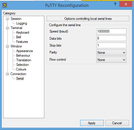
I didn't even consider using the standard Serial Monitor application built into the IDE and instead grabbed a copy of PuTTY and set the serial port up at 1000000 baud.


At this baud rate, the Arduino had no issues and PuTTY correctly decoded the serial stream without issue.  So, if 1M is good, then 2M should be twice as good, right?

Well, not exactly.  at 2,000,000 baud the per character rate is twice the rate, but the overall throughput actually dropped visibily.  By my crude measurements, the throughput dropped by about 15%.  But, it is good to know that Arduino can push serial bits out at a respectable speed.

One side effect to note is that the IDE must override the Serial baud rate in order to program the device.  When running at these very fast serial rates, it can be a bit hit and miss.  If you have trouble, press the reset button and release it just before the compile finishes and you will help it recover.  Another alternative would be to use an external ISP programmer.

Another thing to keep in mind is that the IDE and PuTTY are both going to try and use the same COM port.  The IDE will use it for programming the chip.  PuTTY will use it to monitor the serial output.  In order for the IDE to be able to program the chip, it must be able to open the serial port.  So, you will have to terminate PuTTY before attempting to reprogram the Arduino.

I have read a lot of complaints lately about trying to debug Arduino code with the serial port output.  While upping the serial speed will not help in situations where interrupts are disabled or where time required to output debug data adversely affects the running code, being able to output the data orders of magnitude faster is certainly going to help in general.  If you are doing a lot of edit, compile, flash, run cycles, it might be better to use an ISP programmer so that PuTTY or whatever serial terminal application you use can stay connected to the debug serial port.

In my work with faster embedded processors, 2-3M baud is about the limit even on these devices with much faster core and peripheral clocks.  The Freescale K60 for example is running at 96 MHz in my configuration and at 2M baud on the debug port, I still get data loss, but it is solid at 1M baud.  I think that for high speed output or where you need to output debug information during interrupt processing, it may be a better choice to use SPI for debug output to a dedicated device that can capture and save the output such as a PC with a USB/SPI interface or another Arduino that can write to a storage device such as an SD card.

Thursday, July 2, 2015

KiCAD

Since being laid off at Dynon Avionics, I have been looking around at schematic capture and PCB CAD packages.  Chris at Contextual Electronics has encouraged me to try out KiCAD.  I decided to give it a go and design a small 1 square inch microcontroller board with a full-on ATMega 328 processor and the minimum circuitry necessary to build an (almost) UNO clone.  The "almost" part is the fact that there will be no USB port on the board and it will need be programmed using the ISP connector.

The circuit diagramme I decided on looks like this from KiCAD:


Nothing here that doesn't need to be here for a minimal controller.  I have the entire I/O pin set that can be found on an UNO, plus since I use the TQFP package, I have two additional analogue input pins.

The board layout is pretty dense at one inch square.  Here is the board layout showing all of the layers from KiCAD.  I am not terribly impressed with KiCAD's copper pour capabilities, at least as far as I have explored them, but what do you want for free, eh?


Producing the Gerber files was trivial and I zipped up the lot of them and shipped them off to OSHPark to be manufactured.  Here is the screen shot of their rendering of the gerber files for the front and back of the board.


So, now we wait for the little purple envelope to arrive.  Meanwhile I will collect up the set of parts to build a few of these up.  This was an experiment to enable me to learn KiCAD and at the same time to produce a useful gadget for other projects.  Once I have verified the functionality is correct, I will publish the OSHPark boards so others can order them directly if desired.  At $5 for 3 of them, they are pretty cheap.

Overall, I found KiCAD relatively easy to learn, once I got a couple of key concepts down.  The main one was that hot keys apply to whatever your mouse is hovering over.  I found myself wanting to click to select something before hitting a hot key and this lead to all sorts of grief.  Moving objects once they are placed also needs a lot of work.  Rubber-banding of traces pretty much sucks.  Once I figured out how to drag an object, the best that KiCAD could do is straight line connect all the existing traces.  This ends up being pretty much worthless for anything other than adjustments of a few centimetres and you end up deleting all the traces and redrawing them anyway.

Selection of wires in schematics needs an easy way to select only a line segment or the entire line without having to draw box around it.  When you move the line, it needs to rubber-band the end points.  Straightening out a series of segments needs to collapse them into one segment and it needs to be able to easily break a line segment in two without disconnecting them.  All of these comments also apply to traces in the PCB layout editor.

I did like that KiCAD included the ability to view gerber files, a comprehensive footprint editor as well as building the notion of hierarchical schematics into the product as a key feature.  I cannot however get the bill of materials functionality to work, so I must be doing something wrong.  Always more to learn. 

For a free, open-source product, it is quite compehensive and there are a lot of part footprints available out-of-box and from 3rd parties.  Overall, I would continue to use it for hobby projects.  I would need to try and build at least a four layer board to have an opinion about suitability for commercial projects.

Tuesday, May 26, 2015

Version 1.0 of Si5351 Signal Generator

I have completed version 1.0 of my signal generator.  There will definitely be a revision as there are a number of things still to straighten out, but overall I am pleased with the result.

The 3D printed box with 20% fill on the box walls, was easy to drill, though I recommend a drill press.  I made the top cover thick enough that my controls (rotary encoder and switch) could be threaded into the plastic and no surface nuts required.  This seems to work well, though it remains to be seen how it holds up over time.


The point-to-point wiring inside is a pain in the tush.  Version B will definitely have a single PCB with all the components (display, power switch, rotary encoder, Trinket PRO, Si5351 and battery) plugged into it and mounted on stand-off spacers to the front panel.  I also definitely need to screw down the display.  The friction fit to the panel is good, but not good enough.  The picture below was taken before the Si5351 was installed.


So, overall I am pleased and look forward to using this new addition to my tools.

Monday, May 25, 2015

Si5351 Signal Generator (continued)

My first attempt at 3D printing a case for my signal generator project was, shall we say a good learning process.  The printer printed what I created, but a number of rather fatal flaws in the design indicated the need to scrap it and try again.

Meanwhile, I have decided on the controller that will be dedicated to this project.  Given that the Si5351 and my TFT display are both 3V3 devices, I decided to utilize the Adafruit PRO Trinket 3V3 device.  This is essentially a 3V3, 12 Mhz Arduino Uno without the USB controller and with a couple of I/O pins being dedicated to other purposes and therefore unavailable (pins 2 and 7).


Since I developed the code on the ATMega2560, it seemed that my next task would be to convert the code to run on the ATMega328 processor found in this device and to make some final I/O pin assignments with this device in mind.  The conversion was a little more complicated than I first anticipated due to my sloppy coding on the first go-around.

I didn't want to put header pins on this board for this project, so I used my Arduino Uno to verify the code changes (and to clean up my sloppiness).  I have wired everything using the 3V3 source, but since the I/O pins are 5V on the Uno, I used an NTE4050B buffer to do the level conversion to 3V3 on the pins going to the display.  This will not be necessary once I wire up the intended controller as it is a 3V3 device.  The Si5351 is not shown in this image.


The setup of the 1.6.4 IDE to support the Trinket PRO was fairly straight forward, but here still be dragons.  The Adafruit web site recommends just downloading the IDE with the Adafruit board support definitions already installed.  This is convenient, but creates a set of additional problems which I will likely make the subject of a separate post.

The other thing I learned is that if a class name defined in your code happens to collide with a class name in an existing library in your installation, even if that library is not used in your project, that library will still be compiled and can cause duplicate symbol errors or can surface dependent library missing errors.  I ran into this because I have in my project a file that defines a class for the Si5351, but I also have installed the Adafruit_Si5351 library into the IDE which also defines a class with that name, though in a different name space.  Even though I am not using it, the Adafruit_Si5351 library gets compiled by my project, but since that library depends on the Adafruit_Unified_Sensor library which I had not installed, I got a compile error.  Had the compiler error not occurred, I would have likely gotten link errors.  I need to dig into this in more detail as I believe this to be a bug in the current 1.6.4 IDE from Arduino.cc but need to simplify the reproduction of the issue before filing a bug report.  A lot of work has gone into this version's handling of libraries, but here still be dragons.  My workaround was to delete the Adafruit_Si5351 library from my installation and able to recompile without errors.

So, now I need to make some software changes to allow me to eliminate the extra push button in favor of just the rotary encoder, its push button and the display being the entire user interface.  I also want to provide a mechanism to enable/disable each clock as desired.

My son meanwhile has been busy printing my latest attempt at a case for this project.  I am certain this will not be the final print, but the changes made were to eliminate the plastic posts to hold the display and to make the front panel thicker to give it more rigidity.  I increased the lip size and provided a recess for the display to sit in.  Hopefully it will be a nice friction fit, but if not, I will drill the case and install plastic screws to hold it in place at the corners.


3x4x1.5 inch project box
My son is in the process of dialing in his 3D printer.  This one looks a little rough as he has sped up the head speed considerably in order to cut down on print time.  His extrusion feed rate is a little high and his X vs. Y axis accuracy in this print is about 0.06 mm (about 2.5 mil).  After calibration his accuracy is now about 0.02 mm (about 0.78 mil) so the next print should be a lot cleaner.  His extrusion feed rate causes his interior dimensions to suffer a bit as he is putting down too much material.  He should have that dialed in before he reprints this for me.  We also went to a 20% fill rather than solid, so it will be interesting to see how well that can be drilled.  The top is a tight fit so I will likely need to cut a thumbnail slot along the edge so I can get it off the case once the display fills the hole.  Once he has the new calibrations in place and I have verified my geometry will work with the parts I have in hand, we will print one more and it should look a lot better.

More to come...

Tuesday, May 19, 2015

Si5351 Signal Generator - 3D print of case

Now that the software is in pretty good shape (with a couple lingering issues) I turned my attention to building a case for this project.  Here is a simple front panel design I whipped up (ok, painfully slowly created after many mistakes...) using the online CAD software at www.onshape.com.  They have a pretty cool product offering there and it is certainly sufficient for these kinds of simple projects.


My little display and rotary encoder should fit nicely onto this panel.  As soon as I decide which Arduino board I am going to put into this project, I will work up a nice case back that this will snap into.  Yeah, yeah, this is my first CAD project, so I am 100% certain I will need to redesign it in some fashion.  Like for example, I suspect that I will have to put mounting screws through the panel into posts.  Don't beat me up too badly about my lack of CAD skills.


At this point it is pretty handy to have a son with a 3D printer.  Here it is printing this little guy.  I will go pick it up tomorrow and see if my display will fit into it.


Here it is, finished in 56 minutes.


More to come...

Sunday, May 17, 2015

Uh oh...

I ran across an interesting little anomaly today.  Consider the following Arduino code which prints the result of dividing an unsigned long by a float.

void setup() 
{
  Serial.begin(115200);
  
  uint32_t f = 10000005UL;

  for (int i = 0; i < 10; i++)
  {
    Serial.print(f);
    Serial.print(" - ");
    Serial.println(f/1e6, 6);
    f--;
  }
}

void loop()
{

}

Unfortunately, the following is the output:

10000005 - 10.000005
10000004 - 10.000004
10000003 - 10.000003
10000002 - 10.000002
10000001 - 10.000001
10000000 - 10.000000
9999999  - 10.000000
9999998  - 9.999999
9999997  - 9.999998
9999996  - 9.999997

I guess I am going to have to look into the Print class a bit and see if the error is in the divide operation or the print operation.  Heads up...

UPDATED: Si5351 Signal Generator

I have been updating the UI on my Si5351 signal generator a little bit today.  I think it is about where I want it to be.  I display all three clock frequencies directly at the moment.  There is the notion of a current clock that will be displayed in yellow text.  The other two are displayed in white text.  In the image below, CLK2 is active.  The active clock is the one that will be modified if you rotate the rotary encoder.

Each of the clocks can be set anywhere in the 8 kHz to 160 MHz range.  However, I still have some anomalys as at very low frequencies and at very high frequencies, the clock output does not follow the display.  Obviously, I have more reading to do on the Si5351 datasheet to understand what I am doing wrong.

A button press will cycle through the three clocks.  The rotary encoder press will cycle through the digits of the frequency allowing you to change the tuning rate.  I may get rid of the button and have the rotary encoder button press cycle between selecting the clock (by turning the encoder) and changing the digit that is changed when the encoder is rotated.  Dunno...

I may give some thought to treating one of the clocks as a VFO and another as a BFO and displaying the difference between them for the VFO clock, but setting the output frequency to the sum of the displayed frequency and the BFO frequency.  This would allow for a receive frequency display while the actual VFO frequency is quite different.  In this mode the signal generator could be a convenient receiver display.  This could also be an update for another day.  I also want to provide some indication of which digit will be changed when you turn the encoder.  Currently no indicator is present.

Currently I am running this on my ATMega2560 but the plan is to use an ATTiny85 or perhaps one of the small ATMega328 units such as the Nano, or the Adafruit Trinket Pro.


So, once I get the frequency setting questions answered, I am going to put the arm on my oldest son to 3D print me a small box where I can package up the display, rotary encoder, power switch, Arduino and the Si5351 into a nice battery powered, portable signal generator unit.

Saturday, May 16, 2015

Si5351 Signal Generator

I have been expanding on my initial experiments with the Si5351 today while at the same time getting some experience with my little 1.8" colour TFT display.  This is a nice little display that I picked up locally.  It has an SPI interface and using an ST7735 controller.


I initially was bit-banging the SPI protocol using arbitrary pins on the ATMega2560, but was quite dis-satisfied with the performance.  The display was very laggy and slowed down the entire experience.

By switching to use the hardware SPI support on the ATMega2560 (using pins 51 and 52 for MOSI and SCK signals respectively) the performance improvement was spectacular.  On the UNO, the hardware pins are 11 and 13 for MOSI and SCK respectively.

I am using a modified version of the Adafruit graphics library and the Adafruit ST7735 driver for my experimentation.

I found a couple of problems which I don't know if I can attribute to the Adafruit libraries or to differences with the specific LCD panel I have in hand.  I will have to order one of the Adafruit versions to determine which it is.  I found that the color mappings were reversed between RED and BLUE and also between YELLOW and CYAN.  If I can obtain a version of the Adafruit display I will test again and report my findings.

I set up my Si5351 clock generator and the TFT display as a three frequency signal generator.  There is still some UI work to be done to select between the frequencies to be changed by the rotary encoder, but here is the general idea.  I am reusing my previously published rotary encoder bits in this little project.


I will have the ability to independently set each of the clocks on the Si5351.  At the moment the code sets the initial frequency of each clock and then moves them all when the rotary encoder turns.  I plan to publish the code here when I have it all working satisfactorily.


Performance of the display is now very good, even when updating all three frequencies with the rotary encoder simultaneously.  This might be a good candidate for a little Arduino Nano or other minimal Arduino board to allow packaging this up into a useful signal source.

Monday, May 11, 2015

i2c Scanner

I wanted to share a useful script that I have written to determine the available addresses on Arduino's i2c (pronounced "eye-squared-see") bus.  When attaching new hardware where you may not have the address for the device available, this script can be useful to determine that information.  It is also useful for debugging connectivity issues on an i2c bus.

To use, connect your hardware to the bus clock and data lines.  Apply power and ground your hardware as well.  Run this script and open the serial monitor at 115200 baud.  You can change this speed to suit your preferences.  The serial monitor window will list all of the device addresses found on the bus.

As always, if you need assistance, please let me know by dropping me a note at ko7m at arrl dot net or by posting here and I will try to help you out.

// i2c_scanner
//

#include <Wire.h>

void setup()
{
  Wire.begin();

  Serial.begin(115200);
  Serial.println("i2c Scanner");
}

void printAddress(byte address)
{
  if (address<16) Serial.print("0");
  Serial.println(address, HEX);
}

void loop()
{
  

    Serial.println("Scanning...");
  
    int nDevices = 0;
    
    for(int address = 1; address < 127; address++ ) 
    {
      Wire.beginTransmission(address);
      int error = Wire.endTransmission();
      
      // Just for good measure, try again
      if (error != 0)
      {
//        Serial.print("Error ");
//        Serial.println(error, DEC);
//        Serial.println("Retrying...");
        delay(10);
        Wire.beginTransmission(address);
        error = Wire.endTransmission();
      }
  
      if (error == 0)
      {
        Serial.print("i2c device found at address 0x");
        printAddress(address);  
        nDevices++;
      }
      else if (error == 4) 
      {
        Serial.print("Unknown error at address 0x");
        printAddress(address);
      }    
    }
    if (nDevices == 0)
      Serial.println("No i2c devices found\n");
    else
      Serial.println("");

  // Hang the script
  while (1==1);
}