I have learned a number of things along the way. I am new to control loop implementation and while the algorithms are well known and documented along with plenty of example code, the first thing I learned is that none of that helps you when it comes to tuning the operation of the PID in the specific environment in which it runs.
There are those among us that can describe in glorious detail the math behind all of the theory and implement MatLab simulations of motor transfer functions. That, unfortunately does not describe me. While I have a PhD, it is only in the school of "hard knocks" as my experience is my instructor.
Tuning PID control systems is as much art as science. For a given fader (in my case) one could come up with PID tuning parameters by experimentation that would perform acceptably. However, with the wide variance in acceptable performance from the manufacturers, it is a challenge to replicate that experience across an arbitrary number of faders from the same vendor. My vendor for example specifies that the force required to move the fader is .8 newton which in and of itself is fine, just that the expected acceptable variance from this specification is plus and minus .5 newton. Using a fader with specifications such as these is typical, but results in extreme difficulty when designing to have consistent results across multiple batches of the same fader model. The variation in performance resulted in what initially looked like a 70% failure rate in being able to calibrate them. However, my initial design failed to take into account the fact that the initial batch had very low friction profiles. Comparing the experience to the datasheet, led me to conclude a different design (velocity PID) was required.
A number of desirable design elements are useful when designing control loops for motorized faders.
- Smooth movement
- Accurate positioning
- Stable movement without oscillation
- Able to accommodate a wide variance in friction profiles
- Able to accommodate fairly noisy signals measuring position of the fader
- Able to accommodate accurate measurement of movement velocity
- Sufficient MIPS available to provide tightly coupled feedback loops
My original implementation utilized a PID to control positioning the fader to one of 1024 positions. The PID implementation included most of the fixes for typical PID controller issues which I have previously described. It did a good job of positioning the fader to a give set point, quickly and fairly accurately.
Where it lacked robustness however was in dealing with changes in position that are very small and at an irregular arrival rate and rate of change. Think of moving a control very slowly and sampling it's position on a 100-200 ms basis and using that as the set point for your PID. Goal #1 above suffered greatly. Attempts to tune this with three different sets of tuning parameters achieved reasonable results, but goal #4 was impossible to achieve with a positional PID alone.
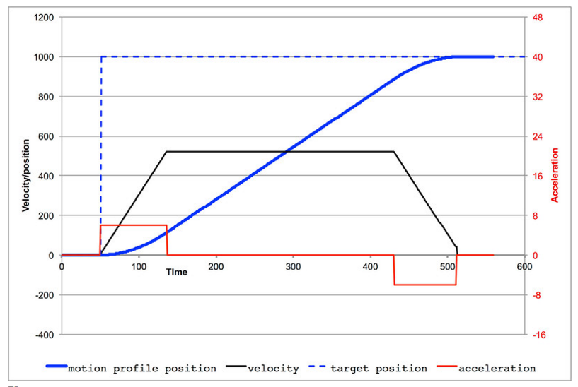
The only way to achieve all of these goals was with a control loop that would set the fader moving in the right direction according to a motion profile and tightly control the velocity of the fader movement. The control loop could apply as much or little force as necessary to keep the movement on the velocity profile desired.
There are (at least) a couple of standard forms of PID algorithms, one that works to control the position of something and the other to control the rate of change of something. I found that I could use the first form (so called analogue PID) to control either in this case. In the positional PID, I measured the position of the fader by reading the DC voltage across the fader potentiometer using an ADC. The input to the PID was the current ADC value read from the fader. The PID would compute the necessary PWM output to drive the motor to the desired position.
In the case of the velocity PID, I kept a history of fader positions over a 5 ms period. The position is calculated every 250 us. The difference between the newest and the oldest position samples provided a velocity with sufficient granularity to be useful. This velocity value (current velocity) was used as the input to the velocity PID. The calculated PWM output value was use to drive the motor to adjust the movement to the desired velocity regardless of varying friction, voltages, etc.
A couple of traps in implementing the vPID (or for that matter, any PID). When tuning, you should always start very non-aggressively and only change one thing at a time. General tips:
- There are hundreds of white papers, publications, youtube videos and the like that describe the process of PID tuning in excruciating detail. They are all useful. Everyone's learning style is different, so use what works for you and toss the rest.
- The proportional gain (Kp) value should be chosen to quickly produce the necessary output PWM value to get you moving in the right direction. Consider the approximate PWM value necessary to move the motor and the estimated maximum velocity error possible when choosing this value. Best to experiment with a too high value and back it off appropriately. The Kp value should kick your motor into action without creating oscillation.
- The correct direction to move is determined by the sign of the positional error. (desired position - actual position). If negative you move one direction, otherwise you move the other direction.
- The integral gain (Ki) value will want to accumulate errors in velocity fairly quickly and so it will likely be greater than Kp. You want accumulating error to be made up in acceleration quickly. Otherwise, your faders will lag both in acceleration and deceleration. Dialing this value up too high will result in overshooting and oscillation.
- The derivative gain (Kd) value will likely be unused in a velocity PID. The presence of noise on the ADC readings is greatly amplified by increasing the Kd value. In my case there is about 30 mv of variance in position calculations for a fader that is not moving. The fact that the fader is 100 mm long and has 1024 positions means that a change in position of one results in a 48 uV change. So, changes in position of 10 or less will be lost in the noise. Sounds like a lot, but 10 positions (out of 1024) on a 100 mm fader is a change in position of about 1 mm. In my experience even with signal processing techniques applied to the ADC value, increasing the Kd value above 1.0 resulted in severe oscillation of the fader. In the end, I set this term to 0.0 disabling it. In a positional PID I found this term to be very useful for flattening out ringing around the positional set point. For velocity, not so much.
One area that is not discussed as much in the various resources available is the importance of not only controlling the velocity, but having the decision about what the desired velocity is be able to change as appropriate. For example, one could merely state that when faders move, they always move at a single constant velocity. This is perhaps a too simple solution. Single set point movements (from A to B) occurring infrequently, this may well be sufficient. Tiny incremental changes you end up with overshooting and backing up (overshooting again) etc. What is necessary is a motion profile that will decide what the velocity should be for a given movement. This can be as complex or simple as will meet your needs.
In my case, I allow the PID tuning to dictate how rapidly the fader is accelerated and the maximum velocity allowed is the set point for the vPID. To determine that set point, I chose to use the distance to the positional set point to determine the velocity. Basically, the further we have to travel, the faster we will go (up to a maximum limit) and then as we approach the set point, we slow down on that same profile. It ends up looking something like this:

This represents three different deceleration profiles that were tried. The blue line represents my original design where up at the top of the graph, we are cruising along at the maximum velocity. As we get close to the target, we begin to decelerate at an initial rate and at the end we increase the rate of deceleration until we stop.
Due to the inherent delays involved in filtering the ADC values, I found that with this profile, I was consistently overshooting my set point position. The amount of overshoot was proportional to the length of the move. Flattening out the curve slightly as seen in the red line, improved the overshoot condition, but not sufficiently. In the end, my profile looks like the yellow line where we begin decelerating a little sooner and decrease the velocity at a slower rate approaching the set point. This has allowed me to accurately position faders and meet all of the requirements above.
There are other details that require attending to. Most DC motor controller chips have the ability to apply a braking action to the motor movement. When coming to a stop, you should definitely apply the braking action. However, be careful that you do not release the brakes too soon. There is a fair amount of inertia in the system and these motors don't stop on a dime. The actual stopping time is a function of the velocity, mass and friction profile. For the simple minded among us (me) this translates into something other than a brake tap. I apply the brakes when in range of where I want to stop plus or minus some delta and then hold them, in my case for about 4 ms before releasing. Without this action, overshooting is a very real problem.
There are other details that require attending to. Most DC motor controller chips have the ability to apply a braking action to the motor movement. When coming to a stop, you should definitely apply the braking action. However, be careful that you do not release the brakes too soon. There is a fair amount of inertia in the system and these motors don't stop on a dime. The actual stopping time is a function of the velocity, mass and friction profile. For the simple minded among us (me) this translates into something other than a brake tap. I apply the brakes when in range of where I want to stop plus or minus some delta and then hold them, in my case for about 4 ms before releasing. Without this action, overshooting is a very real problem.
So with a 250 us cycle of determining the position, keeping 5 ms of positional history to measure the velocity and applying the new PWM value to the motor resulted in very smooth and precise operation. Reducing the fader update rate to 1 ms was also very nice with small steps in position being only slightly more apparent.
I have initially implemented this on a 120 MHz Cortex M4 processor that supports floating point hardware. Now that I have the implementation details worked out, I will be experimenting with simplified fixed point implementations on Arduino hardware and will of course post my code for that as it develops.