Since I cannot seem to turn my brain off on this topic I have been semi-immersed in for a number of weeks, I wanted to jot down a few thoughts on the topic of PID controllers.
My goals in using a PID controller with a mechanical fader that is driven by DC motor are simple, to wit:
- Instantaneous snapping to a new position once loaded into the controller.
- Positional accuracy and repeatability when the same position is loaded.
- Smooth movement of the fader control under PID control when set point changes are small and frequent.
- Tolerant of "stair-stepped" set point changes arriving at non-regular or varying intervals while still maintaining smooth movement.
So far, I have achieved the first two goals. To date, I have been using a positional PID in an attempt to meet all these requirements. A positional PID is one that takes a positional set point and a current position as input and produces the necessary output to drive the fader to its new position. It takes care of acceleration and deceleration as necessary to arrive quickly at the new position.
However, when trying to achieve smooth movement that is quite slow, I find that a positional PID is insufficient for the task for the following reasons:
- A PID tuned to aggressively snap to a new position is a poor experience when trying to achieve slow but smooth changes to the position. The fader tends to be very jerky and/or noisy. The effect looks like a long-term crack user trying to be cool when the authorities arrive. I have attempted to use multiple tuning settings where I reduce the gains of the P, I and D terms, but while it improves things, it is still unacceptable.
- I find that it takes approximately 30% of the motor speed range just to get the fader to move if it is already stopped. Once it overcomes inertia and friction it will suddenly lunge forward and likely overshoot the desired set point if it is close at hand.
- Once the fader is in motion, it takes a lot less energy from the motor to keep it in motion, but there is still a fairly significant dead band in the motor speed range where the fader will stop again if the PID output drops too low. Anytime the PID calculation must reverse direction in order to slow motion, it must necessarily pass through this dead band on both sides of zero.
What is needed for smooth motion out of a PID is to have the PID control the velocity of the motor, not just to move it to a new position. I have attempted to simulate this using a positional PID by limiting the range of the output of the PID to something lower than the maximum speed of the motor when it is desired to be non-aggressive about positioning. However, what I find to be true is that while it helps the overall effect, the results are not sufficiently predictable or repeatable from one fader to the next. They all have their own friction profiles and while they are carefully manufactured, the motor movement transfer function from one fader to the next varies considerably.
So, to provide smooth movement for non-aggressive position changes, what is needed is a velocity PID that will control the speed of the motor according to a motion profile. I will be implementing a trapezoidal motion profile where the motor will accelerate to a maximum speed, hold that speed and then decelerate to a stop at the desired position.
So, I think I need the following:
- Desired velocity - I will calculate desired velocity based off the current positional error. When the desired position changes, we start moving in that direction according to a motion profile.
- Current velocity - I currently calculate this as the derivative term of positional PID. The first derivative of position is velocity.
- A second PID to control motor velocity when being non-aggressive about positioning that will control motor speed according to a motion profile in a tight control loop.
We can visualize position, acceleration and motion profiles as follows:
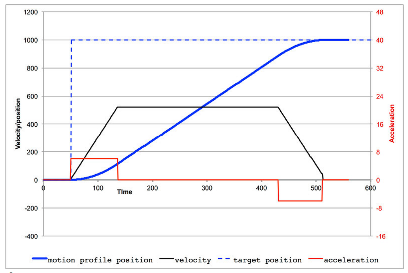
To determine the desired velocity, I will calculate the positional PID error. This is simply the difference between the current position and the desired position. The further I have to go, the faster I will go up to a maximum limit. As the fader moves, the error changes (approaches zero) as the fader approaches its target. The fader loop will calculate the desired velocity as the current position changes towards the target. As friction changes, voltage changes and other external disturbances affect the actual velocity, the PID will calculate the necessary correction in velocity to stay on the motion profile.
More to come...
Jeff,
ReplyDeleteI'm also working on a controller using PID to control DC motors (windshield wiper motors actually) for my custom rotators. I setup 3 different PID routines. One for starting (for x amount of degrees or seconds), one for cruising speed, and another one for positioning within 10 or 15 degrees of the target. I used the current position and calculated target position as inputs to the PID. The target calculation is based on a multiple calculated from the update interval and the difference between the current and previous target. The current target is generated from the multiple and the current time. Every loop generates a new target, then the update from the PC recalculates the multiple. It still needs some tweaking, but I can get smooth tracking, even when grabbing the shaft to try to prevent it from turning. Startup is slow and the deceleration to a stop at the end gets it to within a few degrees. I think I can get that closer with some tuning. PID can keep the current and target positions within a degree while tracking, even if the motor has to stop and start. It's still rough, but I can share what I have with you if you like. It's based on the Arduino Due using optical encoders.
Hi Steven, Thanks for your comments. I appreciate knowing about your experiences and would enjoy seeing what you have produced. I will publish my arduino code when I am convinced it is working satisfactorily.
ReplyDeleteI currently have the hardware posted here - https://github.com/pista01/SEAT
ReplyDeleteMuch of it is 3D printed.
The controller is still not complete, but I'll be posting what I have as soon as I get the park function where I want it. The PID functions are pretty much complete now. I find steppers to be so much easier than DC motors to control. I ended up abandoning the multiple PIDs in favor of just one being used for tracking. Traversing great distances affects the lowest level of the output from the PID once the target is reached. The output never went low enough to stop the motor. Using PID strictly for short distances allows for consistent PID outputs, which is key to stopping and starting the motor. Fun stuff for sure.
Hi Steven, In my experience, I find it best to allow a positional PID to decide when to start and stop if positional accuracy is important. I use an aggressive tuning on the positional PID to get things moving and to correct errors over time. Of course in the system I am working with, there is not a lot of mass and the movement range is 100 mm, so it is a very different problem than an antenna array with a lot of mass and inertia in the system. Unfortunately, other priorities have intervened in the development of the velocity PID, so that part is going to have to wait for now. With my positional PID, I never relied on the PID calculation going to zero in order to stop the motor. The PID tuning would aggressively accelerate and decelerate at the end. However, I picked a range of position values that were "in range" for stopping the movement and went ahead and applied the brakes. Stopping also requires putting the PID in manual mode so that any residual error in position does not continue to accumulate. I also zero the integral term when entering manual mode. Anyway, I will hopefully get on the ball and write up my findings which I will post here. Thanks for sharing your experience and your code.
ReplyDeleteGreat read! I always enjoy your posts—they're clear, insightful, and thought-provoking. You have a knack for making even the most complex topics accessible and interesting. Looking forward to reading more from you!
ReplyDeleteHalltronics
Enrgtech
Data Acquisition Touch Screen Controllers