Saturday, December 31, 2016
Saturday, December 24, 2016
Christmas Thoughts
Well, here we are again, approaching Christmas time.
And I give thanks for the year, even the worst of it was fine.
As I look around me and see Christmas cheer,
I wonder why this mood can't last throughout the year.
Perhaps we'd really like to keep Christmas everyday,
But we lose the spirit, because self gets in the way.
So I write this poem, and put before the eyes of men,
That cannot see others beyond the veil of self.
If we could just see past their faults and love the soul beyond,
We could give the gift of love to make our brothers strong.
Yes, we could give the same gift, in just a different way,
As the gift given the world on that first Christmas day.
I see the end approaching and love is in short supply,
Souls lost and lonely, should cause our hearts to cry.
So may a sense of selflessness guide me throughout the year,
To love all those around me, and spread to them Christmas cheer.
Thursday, December 15, 2016
St. Lucia - 10 Metre Contest
While on St. Lucia, we decided to put a 10 metre station into the contest last weekend. We ran a single station with multiple operators on CW and SSB. Band conditions were pretty abismal, but I think we did pretty well all things considered.
ARRL10M Summary Sheet
Start Date : 2016-12-10
CallSign Used : J68HF
Operator(s) : K0BBC KI8R W6HFP
Operator Category : MULTI-OP
Assisted Category : ASSISTED
Band : 10M
Power : LOW
Mode : MIXED
Gridsquare : FK94MC
Name : Buddies In The Carribean
Address : Manowar Road
Cap Estate Gros Islet
Country : St Lucia
ARRL Section : DX
Club/Team : Minnesota Wireless Assn
Software : N1MM Logger+ 1.0.5995.0
Band Mode QSOs Pts S-P Cty Pt/Q
28 CW 321 1284 49 16 4.0
28 USB 242 484 40 8 2.0
Total Both 563 1768 89 24 3.1
Score : 199,784
Rig : FT-991
Antennas : Buddipole 3 element yagi

Wednesday, December 7, 2016
St. Lucia - Day Four
Today has been non-stop contacts across the entire group on most bands. 17 metres has been hopping most of the day. I was able to work many European contries this morning and this afternoon was spent working US stations.
So far my modest efforts have yielded four continents, 27 states in the US and 29 unique countries. Some of the guys here will work 24 hours a day so it seems, but I tend to go in spurts and then get involved in a project.
Middle of the afternoon one of our group came down to the gazebo to join me for a while and set up his gear. When he powered up the 12V supply for his radio BOOM! He apparently had been working so far from a 110V outlet and the gazebo is 220V only. Oh sigh... We opened up the supply but there had been a rather significant explosion in there and so he tossed it in the bin. Apparently there is one or two of these that bite the dust in this way on every trip of the group down here. I switched everything to 220V before I left home to avoid such nasties. Oh well.
St. Lucia - Day Three
Last evening I was sitting out on the gazebo listening to the surf and watching a cruise ship wander by the north end of the island. It is a lousy picture from a mobile phone, but you can get the idea.

I was able to extricate my gear from the authorities and before heading back to the villa, we had lunch on the beach. The island has lots of dogs running around loose and there was an assortment of them hanging out under the tables looking for a handout.

After getting back to the villa I was able to quickly get on the air and make about 25 contacts in quick succession and later in the evening our wonderful villa hosts brought us a very fine Indian cuisine meal to cap off the evening.


After getting back to the villa I was able to quickly get on the air and make about 25 contacts in quick succession and later in the evening our wonderful villa hosts brought us a very fine Indian cuisine meal to cap off the evening.
Tuesday, December 6, 2016
St. Lucia - DX Map
Just a couple of us up early here on 40 metres right now. This map gives a feeling for how we are doing 7.134 MHz. Come on down and join the fun. Right now J6/K0BBC is at the microphone. Say hi to Matthew on 40 metres from me.


Monday, December 5, 2016
St. Lucia - day two
Today was a lot of antenna building, troubleshooting and for me a bit of frustration at the fact that my gear is still held prisoner by customs. I am starting to adapt to "island time", but when trying to deal with government officials are very friendly and trying to help but offer to have the necessary individual call back when they come in, not being able to find the phone number I am using to talk to them, but they will figure it out, yadda, yadda...
So, frankly I am just happy to be here. I have been so head-down for the last year to 1.5 years, it is just good to not be working and just trying to relax a bit. I did get on 20 metres with a dipole antenna and a borrowed KX3 transceiver today and had fun collecting a couple dozen contacts, mostly in the states, but did get Spain and Canary Island as well. It is fun being the station everyone is trying to work. St. Lucia is not rare by any means, but does draw interest, so I enjoyed that process.
I did manage late in the afternoon to determine what the local officials needed from me in order to be able to release my gear from customs and they agreed to email me copies of the necessary paperwork. My colleague that is in the same boat with one of his pieces of equipment finally got his updated paperwork submitted right at 16:54 (4:54pm) so he didn't hear back today. Hopefully that will be at the top of this guy's in-box in the morning and we can finally go rescue the rest of my luggage. So, I suspect much of tomorrow will be spent driving the length of the island twice.
We went shopping for food and supplies today for the eight of us and I about had a heart-attack when the bill was over ECD $750.00 (East Caribbean Dollars). However, the exchange rate is about 2.7 to 1 so you basically get to divide that number by nearly 3 to see the actual cost in USD (US Dollars).
So, tomorrow looks like we should be on all bands except for 160 and 6 metres. We ran into some problems getting an antenna up on 160 and 6 metres was the last priority for folks, but we have a small group working on it so I suspect we will be on all bands by end of day.
If you want to check out the villa we have for the week, you can read all about it at the website here.
So, I am enjoying hanging out on the deck listening to the surf. We have a bit of wind tonight and it is a nice breeze. If you want to work St. Lucia island tomorrow should be a good time to try it. We usually spot on dx clusters as J6/homecallsign so our frequencies should be easy to find on web sites like http://dxsummit.fi. Just search for J6 and you will find where we are hanging out. Give us a call!
Sunday, December 4, 2016
St. Lucia - day one
Long red-eye flight out of Seattle to Atlanta Saturday night and then another 4 hour flight to Vieux Fort, St. Lucia BWI brought us to a beautiful 85 degree day on the island. The pictures below are from a view point along the east side of St. Lucia where we stopped for a short break on the drive to the north end of the island.


By the time we got to the villa, the sun was setting, so some pictures of the venue will have to wait until tomorrow.
Dinner was supplied to all 8 operators by our hosts and we set about establishing antennas for 80, 40 and 30 metres. We were able to collect 100 contacts as J6/K0BBC on 40 metres before retiring for the night.
On the downside, I had all of my equipment confiscated by St. Lucia customs at the airport as did one other operator. We will attempt to sort out the issues tomorrow and retrieve the impounded equipment. A further downside is that once the proper paperwork SNAFU has been sorted, we have to drive the length of the island again and back which will basically eat an entire day. Oh sigh...
Friday, December 2, 2016
J6/KO7M - St. Lucia
Our license approval was granted yesterday (yay!) for operating on St. Lucia. I will be operating as J6/KO7M. Here is the rig I am taking:


We are still waiting on customs forms which hopefully will arrive today or else we may have a bit of a sit and wait when we arrive on Sunday.
I must admit I felt a little guilty sneaking off the the islands ahead of our first winter snow that is predicted for this week... For about 19 nano-seconds...

Thursday, December 1, 2016
St. Lucia - DX News posting
Hey! We made the ARRL DX news posting today! See the "St. Lucia" listing below! I will be operating at J6/KO7M.
SB DX @ ARL $ARLD049
ARLD049 DX news
ZCZC AE49
QST de W1AW
DX Bulletin 49 ARLD049
From ARRL Headquarters
Newington CT December 1, 2016
To all radio amateurs
SB DX ARL ARLD049
ARLD049 DX news
This week's bulletin was made possible with information provided by
QRZ DX, the OPDX Bulletin, 425 DX News, The Daily DX, DXNL, Contest
Corral from QST and the ARRL Contest Calendar and WA7BNM web sites.
Thanks to all.
RODRIGUES ISLAND, 3B9. Olaf, G0CKV is QRV as 3B9HA and is active
holiday style on the HF bands until December 12. He is also usually
active on 160 and 80 meters around his local sunset from 1400 to
0100z. QSL to M0OXO.
FIJI, 3D2. Chris, VK3FY will be QRV as 3D3FY from December 6 to 14.
Activity will be holiday style on 80 to 10 meters using CW and SSB.
QSL via M0OXO.
MAURITANIA, 5T. Vladimir, UA4WHX is QRV as 5T9VB from Nouakchott.
He is active on 80 to 10 meters using CW, SSB and RTTY. His length
of stay is unknown. QSL to home call.
TONGA, A3. Hiro, JA6WFM is QRV as A31MM from Nuku'alofa until early
2017. Activity is on 160 to 6 meters. QSL via EA5GL.
CAPE VERDE, D4. Larry, OH5XP and Zaba, OH1ZAA are QRV as D4X from
Sal Rei City on Boa Vista Island, IOTA AF-086, until December 5.
Activity is on 40, 30, 20 and 6 meters, and 70 MHz. QSL via OH6GDX.
ANTARCTICA. Francois, F4HLT is QRV as FT3YL from the Dumont
d'Urville Station on the Adelie Land group, IOTA AN-017. Activity
is on 80 to 10 meters using mostly SSB. His length of stay is
unknown. QSL via F6KPQ.
SAINT MARTIN, FS. Paul, K9NU, James, N9TK, John, W9ILY and John,
K9EL are QRV as FS/home calls until December 10. Activity is on the
HF bands using CW, SSB and RTTY. QSL to home calls.
ST. LUCIA, J6. Operators W3FF, W6PNG, W6LDX, KI8R, K0BBC, WJ1B and
KO7M will be QRV as J6/home calls from December 4 to 12. W3FF and
W6HFP will be QRV as J68FF and J68HF, respectively. Activity will
be on 160 to 6 meters from various locations on the island. QSL via
operators' instructions.
SLOVENIA, S5. Special event station S509PMC is QRV during December
and January to call attention to the Peace Messenger City program.
QSL via S59DCD.
CRETE, SV9. Members of the Radio Amateur Association of Chios are
QRV as SZ9/SZ8ARC/p from various locations on Crete until December
3. QSL direct to SZ8ARC.
ANTARCTICA. Oleg, ZS1OIN plans to be QRV as RI1ANA from the
Molodyozhnaya research station until April 2017. Activity is on 160
to 10 meters. QSL to home call.
KAZAKHSTAN, UN. A number of stations are QRV in December with the
UP25 prefix to celebrate the 25th anniversary of Kazakhstan's
independence. QSL via operators' instructions.
UKRAINE, UR. Special event station EO25UD is QRV during December to
celebrate the 25th anniversary of UARL, the Ukrainian national ham
radio club. QSL via UR7UD.
TURKS AND CAICOS ISLANDS, VP5. Dave, W5CW is QRV as VP5/W5CW from
Providenciales, IOTA NA-002, until December 13. Activity is on 160
to 6 meters using CW and SSB. He plans to be active as VP5CW in the
ARRL 160 Meter contest and the upcoming ARRL 10 Meter contest. QSL
direct to home call.
PRINCE EDWARD AND MARION ISLANDS, ZS8. David, ZS1BCE is QRV as ZS8Z
from Marion Island, IOTA AF-021, until May 2018 while working as a
communications technician. Activity is on the HF bands using SSB
and various digital modes when time permits. QSL direct to ZS1LS.
THIS WEEKEND ON THE RADIO. The ARRL 160-Meter Contest, NCCC RTTY
Sprint, QRP 80-Meter CW Fox Hunt, NCCC CW Sprint, TARA RTTY Melee,
Wake-Up QRP CW Sprint, TOPS Activity CW Contest, 10-Meter RTTY
Contest and the SARL Digital Contest are all on tap for this
upcoming weekend.
The ARS Spartan CW Sprint is scheduled for December 6. The CWops
Mini-CWT CW Test, Phone Fray and QRP 40-Meter CW Fox Hunt are
scheduled for December 7.
Youngsters On The Air, YOTA, runs during the month of December. A
number of stations with the YOTA suffix are active for the event.
The ARRL National Parks on the Air event runs during all of 2016 to
mark the 100th anniversary of the National Park Service.
Please see November QST, page 94 and the ARRL and WA7BNM Contest web
sites for details.
NNNN
/EX
Saturday, November 26, 2016
DX-pedition coming up in December
Well, a week from today, I am off to the British West Indies for a week or so of ham radio fun. A group of 8 of us are headed to St. Lucia for a mini DX-pedition. I will be operating 160 thru 6 metres as J6/KO7M. Here is the email to DX News from the trip organizer, Budd Drummond W3FF.
On Nov 25, 2016, at 3:28 PM, Budd Drummond <w3ff@buddipole.com> wrote:
Travel plans are set for the 8th BIC ("Buddies in the Caribbean") mini-DXpedition to St Lucia (J6). Eight operators, some of whom have never experienced the "other side" of a pileup, will be operating from Chateau Devaux on the NE side of St Lucia from December 4th through the 12th, 2016.
This suitcase DXpedition will operate QRP to 100 watt radio stations using Buddipole antennas to make contacts from the villa, the surrounding mountains, and (of course) from St Lucia's superb beaches.
The eight operators are: Paul W6PNG, Thom W6LDX, Mike KI8R, Matt K0BBC, Harold WJ1B, Jeff KO7M, Chris J68HF (W6HFP) and Budd J68FF (W3FF). Ops will preface their own US calls with J6/.
Team members will operate several CW, SSB and/or digital mode stations on 160-6 Meters from the villa while others make contacts with portable setups from remote J6 locations.
Per tradition, meeting and operating with local hams while on J6 is one of our key goals.
QSO confirmation and QSLs will be available via LOTW or direct via information on each operator's www.QRZ.com page.
Saturday, October 1, 2016
Updated Si570 code on GitHub
Well, I have finally updated my Si570 code on GitHub to reflect the changes to fix a bug found and blogged about over two years ago. I described the fix here, but failed to follow through and update the code on GitHub with the changes. Long past due, but glad to have that task off my TODO list.
Saturday, July 23, 2016
PID implementation experiences - UPDATED
I have posted previously about my experiences trying to implement a PID controller. I am controlling linear faders that are motor driven from a remote device. Movement of a control on the remote device results in the physical linear fader following that movement and the remote device following the fader when moved locally.
I have learned a number of things along the way. I am new to control loop implementation and while the algorithms are well known and documented along with plenty of example code, the first thing I learned is that none of that helps you when it comes to tuning the operation of the PID in the specific environment in which it runs.
There are those among us that can describe in glorious detail the math behind all of the theory and implement MatLab simulations of motor transfer functions. That, unfortunately does not describe me. While I have a PhD, it is only in the school of "hard knocks" as my experience is my instructor.
Tuning PID control systems is as much art as science. For a given fader (in my case) one could come up with PID tuning parameters by experimentation that would perform acceptably. However, with the wide variance in acceptable performance from the manufacturers, it is a challenge to replicate that experience across an arbitrary number of faders from the same vendor. My vendor for example specifies that the force required to move the fader is .8 newton which in and of itself is fine, just that the expected acceptable variance from this specification is plus and minus .5 newton. Using a fader with specifications such as these is typical, but results in extreme difficulty when designing to have consistent results across multiple batches of the same fader model. The variation in performance resulted in what initially looked like a 70% failure rate in being able to calibrate them. However, my initial design failed to take into account the fact that the initial batch had very low friction profiles. Comparing the experience to the datasheet, led me to conclude a different design (velocity PID) was required.
A number of desirable design elements are useful when designing control loops for motorized faders.
My original implementation utilized a PID to control positioning the fader to one of 1024 positions. The PID implementation included most of the fixes for typical PID controller issues which I have previously described. It did a good job of positioning the fader to a give set point, quickly and fairly accurately.
Where it lacked robustness however was in dealing with changes in position that are very small and at an irregular arrival rate and rate of change. Think of moving a control very slowly and sampling it's position on a 100-200 ms basis and using that as the set point for your PID. Goal #1 above suffered greatly. Attempts to tune this with three different sets of tuning parameters achieved reasonable results, but goal #4 was impossible to achieve with a positional PID alone.
The only way to achieve all of these goals was with a control loop that would set the fader moving in the right direction according to a motion profile and tightly control the velocity of the fader movement. The control loop could apply as much or little force as necessary to keep the movement on the velocity profile desired.
There are (at least) a couple of standard forms of PID algorithms, one that works to control the position of something and the other to control the rate of change of something. I found that I could use the first form (so called analogue PID) to control either in this case. In the positional PID, I measured the position of the fader by reading the DC voltage across the fader potentiometer using an ADC. The input to the PID was the current ADC value read from the fader. The PID would compute the necessary PWM output to drive the motor to the desired position.
In the case of the velocity PID, I kept a history of fader positions over a 5 ms period. The position is calculated every 250 us. The difference between the newest and the oldest position samples provided a velocity with sufficient granularity to be useful. This velocity value (current velocity) was used as the input to the velocity PID. The calculated PWM output value was use to drive the motor to adjust the movement to the desired velocity regardless of varying friction, voltages, etc.
A couple of traps in implementing the vPID (or for that matter, any PID). When tuning, you should always start very non-aggressively and only change one thing at a time. General tips:

So with a 250 us cycle of determining the position, keeping 5 ms of positional history to measure the velocity and applying the new PWM value to the motor resulted in very smooth and precise operation. Reducing the fader update rate to 1 ms was also very nice with small steps in position being only slightly more apparent.
I have initially implemented this on a 120 MHz Cortex M4 processor that supports floating point hardware. Now that I have the implementation details worked out, I will be experimenting with simplified fixed point implementations on Arduino hardware and will of course post my code for that as it develops.
I have learned a number of things along the way. I am new to control loop implementation and while the algorithms are well known and documented along with plenty of example code, the first thing I learned is that none of that helps you when it comes to tuning the operation of the PID in the specific environment in which it runs.
There are those among us that can describe in glorious detail the math behind all of the theory and implement MatLab simulations of motor transfer functions. That, unfortunately does not describe me. While I have a PhD, it is only in the school of "hard knocks" as my experience is my instructor.
Tuning PID control systems is as much art as science. For a given fader (in my case) one could come up with PID tuning parameters by experimentation that would perform acceptably. However, with the wide variance in acceptable performance from the manufacturers, it is a challenge to replicate that experience across an arbitrary number of faders from the same vendor. My vendor for example specifies that the force required to move the fader is .8 newton which in and of itself is fine, just that the expected acceptable variance from this specification is plus and minus .5 newton. Using a fader with specifications such as these is typical, but results in extreme difficulty when designing to have consistent results across multiple batches of the same fader model. The variation in performance resulted in what initially looked like a 70% failure rate in being able to calibrate them. However, my initial design failed to take into account the fact that the initial batch had very low friction profiles. Comparing the experience to the datasheet, led me to conclude a different design (velocity PID) was required.
A number of desirable design elements are useful when designing control loops for motorized faders.
- Smooth movement
- Accurate positioning
- Stable movement without oscillation
- Able to accommodate a wide variance in friction profiles
- Able to accommodate fairly noisy signals measuring position of the fader
- Able to accommodate accurate measurement of movement velocity
- Sufficient MIPS available to provide tightly coupled feedback loops
My original implementation utilized a PID to control positioning the fader to one of 1024 positions. The PID implementation included most of the fixes for typical PID controller issues which I have previously described. It did a good job of positioning the fader to a give set point, quickly and fairly accurately.
Where it lacked robustness however was in dealing with changes in position that are very small and at an irregular arrival rate and rate of change. Think of moving a control very slowly and sampling it's position on a 100-200 ms basis and using that as the set point for your PID. Goal #1 above suffered greatly. Attempts to tune this with three different sets of tuning parameters achieved reasonable results, but goal #4 was impossible to achieve with a positional PID alone.
The only way to achieve all of these goals was with a control loop that would set the fader moving in the right direction according to a motion profile and tightly control the velocity of the fader movement. The control loop could apply as much or little force as necessary to keep the movement on the velocity profile desired.
There are (at least) a couple of standard forms of PID algorithms, one that works to control the position of something and the other to control the rate of change of something. I found that I could use the first form (so called analogue PID) to control either in this case. In the positional PID, I measured the position of the fader by reading the DC voltage across the fader potentiometer using an ADC. The input to the PID was the current ADC value read from the fader. The PID would compute the necessary PWM output to drive the motor to the desired position.
In the case of the velocity PID, I kept a history of fader positions over a 5 ms period. The position is calculated every 250 us. The difference between the newest and the oldest position samples provided a velocity with sufficient granularity to be useful. This velocity value (current velocity) was used as the input to the velocity PID. The calculated PWM output value was use to drive the motor to adjust the movement to the desired velocity regardless of varying friction, voltages, etc.
A couple of traps in implementing the vPID (or for that matter, any PID). When tuning, you should always start very non-aggressively and only change one thing at a time. General tips:
- There are hundreds of white papers, publications, youtube videos and the like that describe the process of PID tuning in excruciating detail. They are all useful. Everyone's learning style is different, so use what works for you and toss the rest.
- The proportional gain (Kp) value should be chosen to quickly produce the necessary output PWM value to get you moving in the right direction. Consider the approximate PWM value necessary to move the motor and the estimated maximum velocity error possible when choosing this value. Best to experiment with a too high value and back it off appropriately. The Kp value should kick your motor into action without creating oscillation.
- The correct direction to move is determined by the sign of the positional error. (desired position - actual position). If negative you move one direction, otherwise you move the other direction.
- The integral gain (Ki) value will want to accumulate errors in velocity fairly quickly and so it will likely be greater than Kp. You want accumulating error to be made up in acceleration quickly. Otherwise, your faders will lag both in acceleration and deceleration. Dialing this value up too high will result in overshooting and oscillation.
- The derivative gain (Kd) value will likely be unused in a velocity PID. The presence of noise on the ADC readings is greatly amplified by increasing the Kd value. In my case there is about 30 mv of variance in position calculations for a fader that is not moving. The fact that the fader is 100 mm long and has 1024 positions means that a change in position of one results in a 48 uV change. So, changes in position of 10 or less will be lost in the noise. Sounds like a lot, but 10 positions (out of 1024) on a 100 mm fader is a change in position of about 1 mm. In my experience even with signal processing techniques applied to the ADC value, increasing the Kd value above 1.0 resulted in severe oscillation of the fader. In the end, I set this term to 0.0 disabling it. In a positional PID I found this term to be very useful for flattening out ringing around the positional set point. For velocity, not so much.
One area that is not discussed as much in the various resources available is the importance of not only controlling the velocity, but having the decision about what the desired velocity is be able to change as appropriate. For example, one could merely state that when faders move, they always move at a single constant velocity. This is perhaps a too simple solution. Single set point movements (from A to B) occurring infrequently, this may well be sufficient. Tiny incremental changes you end up with overshooting and backing up (overshooting again) etc. What is necessary is a motion profile that will decide what the velocity should be for a given movement. This can be as complex or simple as will meet your needs.
In my case, I allow the PID tuning to dictate how rapidly the fader is accelerated and the maximum velocity allowed is the set point for the vPID. To determine that set point, I chose to use the distance to the positional set point to determine the velocity. Basically, the further we have to travel, the faster we will go (up to a maximum limit) and then as we approach the set point, we slow down on that same profile. It ends up looking something like this:

This represents three different deceleration profiles that were tried. The blue line represents my original design where up at the top of the graph, we are cruising along at the maximum velocity. As we get close to the target, we begin to decelerate at an initial rate and at the end we increase the rate of deceleration until we stop.
Due to the inherent delays involved in filtering the ADC values, I found that with this profile, I was consistently overshooting my set point position. The amount of overshoot was proportional to the length of the move. Flattening out the curve slightly as seen in the red line, improved the overshoot condition, but not sufficiently. In the end, my profile looks like the yellow line where we begin decelerating a little sooner and decrease the velocity at a slower rate approaching the set point. This has allowed me to accurately position faders and meet all of the requirements above.
There are other details that require attending to. Most DC motor controller chips have the ability to apply a braking action to the motor movement. When coming to a stop, you should definitely apply the braking action. However, be careful that you do not release the brakes too soon. There is a fair amount of inertia in the system and these motors don't stop on a dime. The actual stopping time is a function of the velocity, mass and friction profile. For the simple minded among us (me) this translates into something other than a brake tap. I apply the brakes when in range of where I want to stop plus or minus some delta and then hold them, in my case for about 4 ms before releasing. Without this action, overshooting is a very real problem.
There are other details that require attending to. Most DC motor controller chips have the ability to apply a braking action to the motor movement. When coming to a stop, you should definitely apply the braking action. However, be careful that you do not release the brakes too soon. There is a fair amount of inertia in the system and these motors don't stop on a dime. The actual stopping time is a function of the velocity, mass and friction profile. For the simple minded among us (me) this translates into something other than a brake tap. I apply the brakes when in range of where I want to stop plus or minus some delta and then hold them, in my case for about 4 ms before releasing. Without this action, overshooting is a very real problem.
So with a 250 us cycle of determining the position, keeping 5 ms of positional history to measure the velocity and applying the new PWM value to the motor resulted in very smooth and precise operation. Reducing the fader update rate to 1 ms was also very nice with small steps in position being only slightly more apparent.
I have initially implemented this on a 120 MHz Cortex M4 processor that supports floating point hardware. Now that I have the implementation details worked out, I will be experimenting with simplified fixed point implementations on Arduino hardware and will of course post my code for that as it develops.
Saturday, July 9, 2016
Fox hunt day 1
The wind and rain today didn't seem to stifle fox hunters out looking for my four foxes. Unfortunately, it seems I will need to make some changes as with the very short loop antennas that are in use for direction finding, folks were having trouble hearing the foxes without getting quite close to them first, at least for the 30 metre frequency. Not too many takers on the VHF frequencies, so I think for tomorrow I will turn off the 2 metre beacon and just use the 30 metre CW beacon. I will need to add a counterpoise to the antenna however to increase it's range a bit. I could hear all the foxes with a small handheld Grundig receiver using a short whip antenna, but most folks reported having to get quite close to the transmitter before they could hear it at all.
With the kind of event we are running here, folks are not going to traipse all over the place to get to the point where they can hear the beacon. They need to be able to hear them (or most of them) from the starting point or they will give up before venturing too far afield.
So, some lessons learned. I will increase the range and verify they can all be heard at the starting point with the simple loop antennas we are using for tomorrow's group of hunters.
Sunday, June 19, 2016
Fox Hunt Progress Update
In a series of previous posts (search this blog for "fox hunt"), I have described a fox hunt transmitter for simultaneous HF and VHF fox hunting.
I have made some slight changes to the code to select a VHF frequency based on serial number and made different recordings for the voice announcement on VHF that will identify the fox beacon code. I have reduced the audio sample rate to 8 kHz and set the deviation to +/- 12.75 kHz.
I decided that given I don't have any experience yet with the VHF fox that I would put each of them on a different VHF FM simplex frequency based on it's serial number.
SN 0 - 147.420
SN 1 - 147.435
SN 2 - 147.450
SN 3 - 147.465
Once I have some experience with locating a VHF fox, I may experiment with putting multiple foxes on the same frequency and staggering their announcements.
Here you can see my four little foxes ready for their fox den. The eye bolts on the end will be attached to lengths of wire to provide both the HF and VHF antenna connections and a convenient way to hang the fox up in a tree or other hiding place. The end caps are not glued in place, so they can be removed to facilitate repairs, firmware changes or battery replacement. They will keep dust and rain at bay however quite nicely.
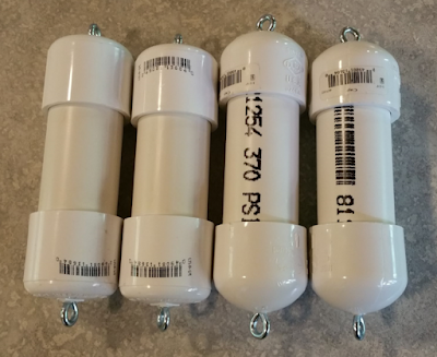
A standard 9V battery powers these devices for several days with only the HF beacon running on CW. It remains to be seen how much the VHF FM mode reduces that battery life figure.
I have made some slight changes to the code to select a VHF frequency based on serial number and made different recordings for the voice announcement on VHF that will identify the fox beacon code. I have reduced the audio sample rate to 8 kHz and set the deviation to +/- 12.75 kHz.
I decided that given I don't have any experience yet with the VHF fox that I would put each of them on a different VHF FM simplex frequency based on it's serial number.
SN 0 - 147.420
SN 1 - 147.435
SN 2 - 147.450
SN 3 - 147.465
Once I have some experience with locating a VHF fox, I may experiment with putting multiple foxes on the same frequency and staggering their announcements.
Here you can see my four little foxes ready for their fox den. The eye bolts on the end will be attached to lengths of wire to provide both the HF and VHF antenna connections and a convenient way to hang the fox up in a tree or other hiding place. The end caps are not glued in place, so they can be removed to facilitate repairs, firmware changes or battery replacement. They will keep dust and rain at bay however quite nicely.
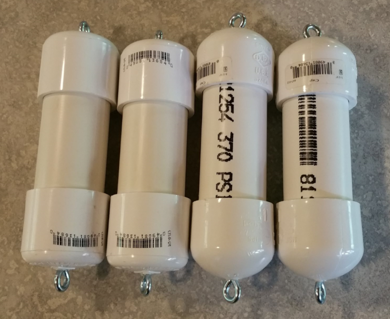
A standard 9V battery powers these devices for several days with only the HF beacon running on CW. It remains to be seen how much the VHF FM mode reduces that battery life figure.
Monday, June 6, 2016
Summertime! Let's get out there and fox hunt! (Part 3)
In this final installment describing my fox hunt transmitter, I provide the final bit of "glue" code that ties the other two pieces together.
As in previous modules, the constants section defines the frequency of the crystal used to clock the Propeller chip and indicates the PLL multiplier in use. In this case, the physical crystal is 5 MHz and a 16x multiplier is provided to clock the Propeller chip at 80 MHz.
'Salmoncon Fox Hunt Transmitter
'
' ko7m - Jeff Whitlatch
'
' The Salmoncon fox hunt transmitter is a simultaneous HF and VHF beacon transmitter
' typically used for RDF (Radio Direction Finding) events. As implemented, one HF CW and
' one VHF FM voice beacon are provided simultaneously.
'
CON
_CLKMODE = XTAL1 + PLL16X
_XINFREQ = 5_000_000
WMin = 381 'WAITCNT-expression-overhead Minimum
Next we define the other modules that are included in the system from Part 1 describing the HF CW beacon and Part 2 describing the 2 metre FM beacon. The clock module is described below. In my case I gave these modules the quoted names you see here with the .spin suffix added to the file name.
OBJ
HFFox : "ko7mHFCWFox" ' HF CW beacon on 30 metres
FMFox : "ko7m2MFMFox" ' 2m FM voice beacon on 146.52 MHz
Clock : "ko7mClock" ' 1 second clock
The initialization code sets up the FM beacon to run every 10 seconds and starts the clock running.
PUB doInitialize
Sync := 10 ' FM beacon runs every 10 seconds
Clock.Start ' Start up the clock module
The main function calls the initization function above and then starts the HF CW transmitter running in its own core. The FM transmitter runs on this core, so we go into a loop and call it's Main function every 10 seconds. Pretty simple, eh?
PUB Main
doInitialize ' Initialize the Fox Hunt beacon
HFFox.Start ' Start the HF beacon in its own cog
repeat
FMFox.Main ' Run the 2M beacon
repeat while Clock.getSeconds // Sync
delay(100)
The clock module I will not describe line-by-line. Suffice it to say that its function is to increment a 32 bit integer every 1 second and to provide a way to retrieve the current counter value. The full source code can be seen at the end of this posting.
So, that is it! I hope you find my little fox hunt transmitter of some value. If there is interest in having a pre-compiled hex file available, I will put it up on a web page or FTP link somewhere and update this post to contain the link.
As always, I am happy to help if you get stuck. The Propeller chip is a bit different but quite functional and capable and provided me with the ability to create a rather unique solution in a very tiny package. Drop me a note here or at ko7m at arrl dot org and I will be happy to help. So, get out there and host some fox hunts this summer.
73's de Jeff - ko7m

Below I provide the entire source code for the top level controller and the clock module for your convenience. These should be put into separate .spin files for compilation.
'Salmoncon Fox Hunt Transmitter
'
' ko7m - Jeff Whitlatch
'
' The Salmoncon fox hunt transmitter is a simultaneous HF and VHF beacon transmitter
' typically used for RDF (Radio Direction Finding) events. As implemented, one HF CW and
' one VHF FM voice beacon are provided simultaneously.
'
CON
_CLKMODE = XTAL1 + PLL16X
_XINFREQ = 5_000_000
WMin = 381 'WAITCNT-expression-overhead Minimum
OBJ
HFFox : "ko7mHFCWFox" ' HF CW beacon on 30 metres
FMFox : "ko7m2MFMFox" ' 2m FM voice beacon on 146.52 MHz
Clock : "ko7mClock" ' 1 second clock
VAR
LONG Sync
PUB Main
doInitialize ' Initialize the Fox Hunt beacon
HFFox.Start ' Start the HF beacon in its own cog
repeat
FMFox.Main ' Run the 2M beacon
repeat while Clock.getSeconds // Sync
delay(100)
PUB doInitialize
Sync := 10 ' FM beacon runs every 10 seconds
Clock.Start ' Start up the clock module
PUB delay(Duration)
waitcnt(((clkfreq / 1_000 * Duration - 3932) #> WMin) + cnt)
The clock module code follows:
' Clock module
'
' Simple module to provide a second counter for synchronizing events.
'
' ko7m - Jeff Whitlatch
'
'
CON
_clkmode = xtal1 + pll16x 'Standard clock mode * crystal frequency = 80 MHz
_xinfreq = 5_000_000
WMin = 381 'WAITCNT-expression-overhead Minimum
delayMS = 1000 ' Clock updates every second
VAR
LONG SecondCounter
LONG Stack[16]
BYTE Cog
PUB Start : fSuccess
SecondCounter := 0
fSuccess := (Cog := cognew(clock, @Stack) + 1) > 0
PUB Stop
if Cog
cogstop(Cog~ - 1)
PUB getSeconds : sec
sec := SecondCounter
PUB delay(Duration)
waitcnt(((clkfreq / 1_000 * Duration - 3932) #> WMin) + cnt)
PUB Clock ' Runs In its own COG
repeat
delay(delayMS) ' Update second counter every 1000 ms
SecondCounter++ ' Should be good for 2^32 seconds or about 136 years
Sunday, June 5, 2016
Summertime! Let's get out there and fox hunt! (Part 2)
In my previous post, I described the first half of a hidden transmitter (fox) implemented using a Propeller Mini board for an HF CW beacon and some simple firmware. In this installment, I will describe the 2 meter FM portion of the firmware.
My first thought was to implement the VHF beacon transmitter using the same design as used on the HF CW beacon except to use MCW rather than CW using FM modulation of the 2 meter carrier.
This approach is simple enough, but rather than generate the audio CW signal to FM modulate the carrier, why not just modulate it with any recorded audio? In this way a vocal announcement could be use to identify the beacon.
In my case I decided to use a free Windows application called "Audacity" to make an audio recording of a 2 second announcement "Salmoncon Fox Hunt" and save it as a .wav file. The file is exported from Audacity as a 11.025 kHz sample rate, 8 bit, monaural recording which is then loaded into the program flash of the Propeller chip and used to FM modulate the 146 MHz carrier. At 11.025 kHz, two seconds of audio will be 11025 * 2 bytes plus 44 bytes of wav file header.
Using 8 bit samples, the sample byte is multiplied by 32 and added to the frequency being generated. SInce this deviation of the carrier frequency is happening at an audio rate, we have achieved FM modulation of the transmitter. This yields a maximum of 256 * 32 = 8.192 kHz of frequency deviation. A multiplier of 58 will get you to just shy of 15 kHz. For my purposes, 8 kHz is just fine.
Let's take a quick walk through the code as it is pretty trivial. Up top we see the same structure defining the necessary constants used in the code. In the comments we can see the formula for calculating the value used to set the RF frequency. For example:
146520000 / (16 * 80000000) * 2^32 = 491639537.664. Truncating to an integer is sufficient for this purpose. This value is loaded into the counter FRQA register to generate the desired 146.52 MHz signal.
' 2 meter FM fox hunt beacon
'
' ko7m - Jeff Whitlatch
'
' FRQx = frequency / (16 * CLKFREQ) * 2^32
'
' Propeller manual recommends limiting upper frequency to 128 MHz for best stabillity
' We of course ignore such advice and utilize it at 146.52 MHz
CON
_clkmode = XTAL1 + PLL16X
_xinfreq = 5_000_000
WMin = 381
RFPin = 8
FRQAvalue = 491_639_537 ' For 146.52 MHz (146520000 / (16 * 80000000) * 4294967296)
sampleRate = 11025 ' 11.025 kHz audio
waitKeyDn = 1000 ' Delay before audio starts with key down
waitKeyUp = 2000 ' Delay after audio ends before key up
wavHdrSize = 44 ' Size of wave file header
devScale = 5 ' deviation scaler for audio samples (256 * 32 = 8.192 kHz)
The only local variables used are when we are running this code on its own core. In this case we define the Stack space required and keep track of which core (cog) was assigned.
VAR
LONG Stack[16]
BYTE Cog
The Main function initializes the VHF beacon and runs the main function. To enable this code to be run on separate cores, Start and Stop functions are provided.
PUB Main
doInit
doBeacon
PUB Start : fSuccess
fSuccess := (Cog := cognew(Main, @Stack) + 1) > 0
PUB Stop
if Cog
cogstop(Cog~ - 1)
The doInit function sets up the RF pin as an output and configures the counter to enable RF generation on 2 metres
pri doInit
DIRA[RFPin]~~ ' Set RF pin as an output
CTRA := constant(010_111 << 23) + RFPin ' Configure the counter
This is the main function of the beacon. The CPU clocks per sample of audio at the audio sample rate is calculated. The index of the first byte of audio is calculated and RF generation of a carrier is initiated. After a brief pause, each byte of the audio data is used to FM modulate the carrier. Once the entire message is sent, the carrier is kept on for a couple seconds to help fox hunters zero in on the transmitter. The RF is then shut down and after a short delay, the process repeats.
PRI doBeacon | p, time, clocksPerSample
clocksPerSample := clkfreq / sampleRate ' System clocks per audio sample
p := constant(@audioStart + wavHdrSize) ' Pointer into our audio data just past the wav file header
FRQA := FRQAvalue ' Go key down
delay(waitKeyDn) ' Wait before modulation starts
time := cnt
' Play the audio file once through
repeat while p++ < @audioEnd
FRQA := FRQAvalue + byte[p] << devScale ' Scale amplitude byte by 32 (2^8 * 32 = 8.192 kHz deviation max)
waitcnt(time += clocksPerSample) ' Wait until time for the next sample
delay(waitKeyUp) ' Delay before dropping carrier
FRQA := 0 ' Turn off NCO
pri delay(Duration)
waitcnt(((clkfreq / 1_000 * Duration - 3932) #> WMin) + cnt)
The audio data is stored in the data secion of the code. Since there is only 64 kb of ROM on the device, the amount of recorded data is limited to available ROM space. If desired, the audio sample rate could be reduced to 8 kB to enable increased message length. The actual audio data is stored in the "foxhunt.wav" file specified in the same directory as this file.
DAT
audioStart byte
File "foxhunt.wav" ' Audio data to be transmitted
audioEnd byte 0
Ok, so now we have two beacons that can be used independently. In my next installment, I shall tie these two modules together so they can be used simultaneously. I will also provide a hex file of the compiled code should you not wish to mess with installing the Propeller Tools for code development.
Improvements of course could be made. Any sample rate of audio could be used and the encoded rate read from the .wav file header for example rather than needing to change a constant for a different sample rate file. Let your imagination be your guide. Have fun and as always if you get stuck, drop me a note at ko7m at arrl dot net and I will try my best to help you out.
See you in the next installment. For your convenience, the entire source code is reproduced below.
' 2 meter FM fox hunt beacon
'
' ko7m - Jeff Whitlatch
'
' FRQx = frequency / (16 * CLKFREQ) * 2^32
'
' Propeller manual recommends limiting upper frequency to 128 MHz for best stabillity
' We of course ignore such advice and utilize it at 146.52 MHz
CON
_clkmode = XTAL1 + PLL16X
_xinfreq = 5_000_000
WMin = 381
RFPin = 8
FRQAvalue = 491_639_537 ' For 146.52 MHz (146520000 / (16 * 80000000) * 4294967296)
sampleRate = 11025 ' 11.025 kHz audio
waitKeyDn = 1000 ' Delay before audio starts with key down
waitKeyUp = 2000 ' Delay after audio ends before key up
wavHdrSize = 44 ' Size of wave file header
devScale = 5 ' deviation scaler for audio samples (256 * 32 = 8.192 kHz)
VAR
LONG Stack[16]
BYTE Cog
PUB Main
doInit
doBeacon
PUB Start : fSuccess
fSuccess := (Cog := cognew(Main, @Stack) + 1) > 0
PUB Stop
if Cog
cogstop(Cog~ - 1)
pri doInit
DIRA[RFPin]~~ ' Set RF pin as an output
CTRA := constant(010_111 << 23) + RFPin ' Configure the counter
PRI doBeacon | p, time, clocksPerSample
clocksPerSample := clkfreq / sampleRate ' System clocks per audio sample
p := constant(@audioStart + wavHdrSize) ' Pointer into our audio data just past the wav file header
FRQA := FRQAvalue ' Go key down
delay(waitKeyDn) ' Wait before modulation starts
time := cnt
' Play the audio file once through
repeat while p++ < @audioEnd
FRQA := FRQAvalue + byte[p] << devScale ' Scale amplitude byte by 32 (2^8 * 32 = 8.192 kHz deviation max)
waitcnt(time += clocksPerSample) ' Wait until time for the next sample
delay(waitKeyUp) ' Delay before dropping carrier
FRQA := 0 ' Turn off NCO
pri delay(Duration)
waitcnt(((clkfreq / 1_000 * Duration - 3932) #> WMin) + cnt)
DAT
audioStart byte
File "foxhunt.wav" ' Audio data to be transmitted
audioEnd byte 0
Subscribe to:
Posts (Atom)