
Monday, March 30, 2015
New toys in the Post
When I got home today, I had a package waiting for me from the good folks at Freetronics down in Australia. After reading my recent posts on experiments with the Arduino Due, they asked if they could send me their Due for use in my future experiments. I received a nice package with their Due which has onboard Ethernet. Freetronics is known for their power over Ethernet solutions. They also provided a nice little prototype board as well as a 4 port Ethernet power injector. So thanks Freetronics! I can't wait to check out the new board!
Thursday, March 26, 2015
Minima - Again?
I have been back playing around a little bit with the Minima code the last couple of days. I have also been looking at TFT displays for my microcontroller projects. While not really a hobbyist price range, I stumbled over a nice group of displays from 4D Systems in Australia (www.4dsystems.com.au) that allow you to easily create some very nice displays without a lot of programming and simple serial interfaces to them that operate at high speeds and offload graphics drawing tasks to the display which sports its own processor.
You design the display layout on the desktop computer and save the user-interface elements to a micro-SD card that then plugs into the display. Interface to the micro-controller is transmit/receive data, ground, 5V and reset. Easy Peasy...
Here is an example display for the Minima that I have been tinkering with. Not bad for a first attempt. (I am not the best UI designer... Ok, I suck at it...)

So, it will be fun to see where this leads. Being a touch screen (they have both TFT and CAP Touch available) it can be used for input as well as output. I am using the simplified tools that have a selection of UI elements that can be placed, sized and programmed on the display as well as Arduino and Raspberry PI libraries to encapsulate the serial communications protocol. There is also the ability to talk to the lower level primitives, so we will have to scope that out as well.
More to come...
You design the display layout on the desktop computer and save the user-interface elements to a micro-SD card that then plugs into the display. Interface to the micro-controller is transmit/receive data, ground, 5V and reset. Easy Peasy...
Here is an example display for the Minima that I have been tinkering with. Not bad for a first attempt. (I am not the best UI designer... Ok, I suck at it...)
So, it will be fun to see where this leads. Being a touch screen (they have both TFT and CAP Touch available) it can be used for input as well as output. I am using the simplified tools that have a selection of UI elements that can be placed, sized and programmed on the display as well as Arduino and Raspberry PI libraries to encapsulate the serial communications protocol. There is also the ability to talk to the lower level primitives, so we will have to scope that out as well.
More to come...
Sunday, March 8, 2015
Arduino Due - USB keyboard with PSK31 encoder
I have spent a few minutes today building an example PSK31 keyboard based on the Arduino Due and the recent work I posted to generate PSK31 from an Arduino Uno or Mega2560.
Firstly, I will discuss the necessary changes to implement my PSK31 encoder on the Due and then the changes needed to incorporate a USB keyboard as the beginnings of a full-function PSK31 encoder.
Readers of my previous blog posts on Generating PSK31 with an Arduino (a total of 4 posts, the other three of which are linked with the referenced article) will know that I generate PSK31 tones using a timer interrupt to construct the audio waveform from (un-optimized) memory tables of sinusoidal information. If interested, you should also check out the recent excellent work by Jim Harvey (WB8NBS) to optimize the size of memory-resident sinusoidal data from my previous work on software DDS on the Arduino.
Generating timer interrupts on the Due is quite flexible and I have previously posted an extensive article on the topic of using Timer Counters on the Due. Please have a look for all the gory details.
In porting my PSK31 Arduino code over to the Due, the main change that was necessary was surrounding how timers work.
// Set up Timer/Counter (TC)
void TimerStart(Tc *tc, uint32_t channel, IRQn_Type irq, uint32_t freq)
{
pmc_set_writeprotect(false);
pmc_enable_periph_clk(irq);
TC_Configure(tc, channel, TC_CMR_WAVE | TC_CMR_WAVSEL_UP_RC |
TC_CMR_TCCLKS_TIMER_CLOCK1);
uint32_t rc = VARIANT_MCK / 2 / freq;
TC_SetRC(tc, channel, rc);
TC_Start(tc, channel);
tc->TC_CHANNEL[channel].TC_IER= TC_IER_CPCS; // | TC_IER_CPAS;
tc->TC_CHANNEL[channel].TC_IDR=~(TC_IER_CPCS); // | TC_IER_CPAS);
NVIC_EnableIRQ(irq);
}
My previous article on Timers on the Due uses a variant of this function to set up a timer to interrupt at an appropriate rate to generate all phase points of a sinusoid at the desired freqency.
The only change here is to use a different timer clock. In this case I chose to use TIMER_CLOCK1 which is the master clock (84 MHz) divided by 2. We divide this by the desired frequency of 31.25 kHz and set a counter match interrupt at this value. The counter will now count (at 42 MHz) up to 1344 and fire an interrupt, effectively dividing 42 MHz down to 31.250 kHz.
The timer handler as described in my article on Due timers is called TC3_Handler because we are using Timer/Counter 1 channel 0. Please see the table in my previous article for the mapping of Timer/Counter channels to handler function names.
// Grab the next phase point from the table and
// set the amplitude value of the sinusoid being
// constructed. For a one bit, set 500 phase points
// (20 amplitudes of 25 samples each) to ramp
// down to zero and then immediately back up to full
// amplitude for a total of 1024 phase points.
//
// For a zero bit, there is not amplitude or phase
// change, so we just play 20 phase points of
// full amplitude data 25 times for a total of 1000
// phase points.
//
// Each end of the ramp-up table starts with a zero
// crossing byte, so there is one extra byte in
// the table (501 entries). Ramping up plays bytes
// 0 -> 499 and ramping down plays bytes 500 -> 1
// allowing each direction to start at the zero
// crossing point.
//TC1 ch 0
void TC3_Handler()
{
TC_GetStatus(TC1, 0); // Reset TC
// Set current amplitude value for the sine wave
// being constructed taking care to invert the
// phase when processing the table in reverse order.
analogWrite(DAC0, (*pbSine * ix * phase) & 0xff);
pbSine += ix;
// At the half bit time, we need to change phase
// if generating a zero bit
if (0 == --cbHalfBit)
{
cbHalfBit = 500; // Reset 1/2 PSK bit time phase counter
// Get the next varichar bit to send
if (fFullBit)
{
// Count the number of sequential zero bits
if (fSendOne = vcChar & 1) cZeroBits = 0; else cZeroBits++;
// Shift off the most least significant bit.
vcChar >>= 1;
// If we have sent two zero bits, end of character has occurred
if (cZeroBits > maxZeroBits)
{
cZeroBits = 0;
// If send buffer not empty, get next varicode character
if (head != tail)
{
// Assumes a 256 byte buffer as index increments modulo 256
vcChar = varicode[rgchBuf[head++]];
}
else
if (maxZeroBits > 2) stopTX(); else maxZeroBits = 4;
}
}
fFullBit = !fFullBit; // Toggle end of full bit flag
// When we get done ramping down, phase needs to
// change unless we are sending a one bit
if (ix < 0 &&!fSendOne) phase = -phase;
}
// At the end of the table for the bit being
// generated, we need to change direction
// and process the table in the other direction.
if (0 == --cbDirection)
{
cbDirection = fSendOne ? 20 : 500;
ix = -ix;
}
}
I added two functions to start and stop the PSK engine as appropriate.
// True if the PSK engine is currently sending data
uint8_t fIsSending = false;
// Start the PSK engine transmitting if it is not already
void startTX()
{
if (fIsSending) return;
// Set timer to 31.25 kHz for a period of 32 us and start it
TimerStart(TC1, 0, TC3_IRQn, 31250);
fIsSending = true;
}
// Stop the PSK engine transmitting
void stopTX()
{
TC_Stop(TC1, 0);
fIsSending = false;
}
I also put the DAC into 8 bit mode to be compatible with my sinusoidal tables, though 12 bit mode could be easily accomodated.
// Use 8 bits in analogue conversions
analogWriteResolution(8);
analogReadResolution(8);
// Include the keyboard controller library to add USB keyboard support
#include <KeyboardController.h>
// Initialize the USB controller
USBHost usb;
// Attach keyboard controller to USB
KeyboardController keyboard(usb);
I then, added some example keyboard support functions to detect when a key is pressed and to enable some simple example keyboard macros.
// Keyboard functionality follows
// Intercept key release
void keyReleased()
{
char rgchTemp[] = {0, 0};
const char *szText = &rgchTemp[0];
int cchText = 0;
switch (keyboard.getOemKey())
{
case 58: // F1
szText = "\nCQ CQ CQ de ko7m ko7m ko7m"
"\nCQ CQ CQ de ko7m ko7m ko7m"
"\nCQ CQ CQ de ko7m ko7m ko7m CN87xp pse k\n";
break;
case 59: // F2
szText = "\n Me: Jeff - ko7m"
"\nLoc: Redmond, Washington USA"
"\nGrd: CN87xp"
"\nQSL: eQSL, direct or bureau"
"\nRig: Homebrew SSB transceiver"
"\nAnt: G5RV at about 8 metres"
"\nPSK: Homebrew Arduino Due software"
"\n";
break;
case 60: // F3
szText = "\n\nSo, back to you!\n";
break;
case 61: // F4
szText = "\nTnx for the nice QSO"
"\nBest of 73's to you and yours!"
"\n";
break;
case 62: // F5
szText = " de jeff -ko7m\n\n";
break;
case 40: // CR
szText = "\r\n";
break;
default:
rgchTemp[0] = keyboard.getKey();
rgchTemp[1] = 0;
break;
}
cchText = strlen(szText);
while (cchText--)
rgchBuf[tail++] = *szText++;
startTX(); // Start the PSK engine if it is stopped
}
That is about it! A couple of things are left to the reader to provide as desired. I have not created a complete turn-key solution, but rather have provided the main building blocks for you to base a complete solution of your own design on as desired.
- You get to type blind. There is no display currently on my Due, nor am I using the serial terminal in order to provide feedback as to what you are typing. This could be done with a local LCD display, the serial monitor screen or a separate display connected to the second USB port or connected to any of the serial ports.
- You must provide the necessary DAC buffer electronics in order to not load the DAC pin of your Due as it will not source much current before the output FET blows up. I am using a simple LM386-based powered computer speaker with a DC blocking capacitor in series with a current limiting resistor.
IMPORTANT: You will blow the output FET on your Due if you hook low impedance speakers or headphones directly to the DAC pin - don't do it.


The keyboard connects to the Due on the "Native USB Port" (right hand USB connector, furthest from the power connector) and the PC connects to the programming port (left hand USB connector, nearest the power connector).

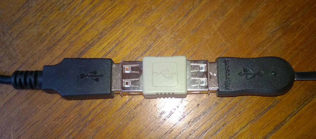
Normally, you would use a USB OTG (USB on-the-go) cable to connect a keyboard to the Due.

However, since my cable has this nice right-angle connector on the micro-USB end of the cable, it prevented me from using it on the Due when the programming cable is plugged in. So I instead used a standard USB to micro-USB cable with a female-to-female adapter between that cable and the keyboard cable.
PS2 keyboards could be easily implemented on the Arduino UNO and Mega2560. Some reference information can be found here. Any USB host functionality required to support HID devices such as a USB keyboard would be a rather large effort to implement. PS2 support is much simpler and would be a good option for non-Due Arduino boards.
There is a small start-up delay (of a couple seconds) on the USB host functionality, so if you power on the Due and start typing immediately, there may be some keystrokes that are lost. I have not investigated yet why this occurs in the standard USB library.
Have fun with this and let me know if you adapt any of this to your purposes. I have included the complete listing of my code below for your reference.
As always, if you encounter problems or questions, I am happy to try and help. Drop me a note by replying here or by email at ko7m at arrl dot net.
// PSK31 audio generation - Arduino Due version
// Jeff Whitlatch - ko7m
// Include the keyboard controller library to add USB keyboard support
#include <KeyboardController.h>
// We are going to generate a 1 kHz centre frequency tone.
// Each 1 kHz cycle of the sinusoid will be generated from
// 32 eight bit amplitude samples. The period of a 1 kHz tone
// is 1 ms. Each of the 32 samples per cycle has a period
// of 31.25 us. We will construct each sinusoid from a 32 byte
// per cycle lookup table of amplitude values ranging from
// 0x00 to 0xff where the zero crossing value is 0x80.
// The PSK31 character bit time is 31.25 ms constructed of 1024
// samples. A binary zero is represented by a phase reversal
// while a binary 1 is represented by the lack of a phase reversal.
// Characters are encoded with a variable bit length code (varicode)
// where the length of each character is inversely
// proportional to the frequency of use in the english language
// of that character. Characters are encoded with a bit
// pattern where there are no sequential zero bits. Two zero bits
// in a row signify the end of a character.
// Varicode lookup table
//
// This table defines the PKS31 varicode. There are 128 entries,
// corresponding to ASCII characters 0-127 with two bytes for each entry.
// The bits for the varicode are to be shifted out LSB-first.
//
// More than one zero in sequence signifies the end of the character.
// For modulation, a 0 represents a phase reversal while a 1
// represents a steady-state carrier.
uint16_t varicode[] = {
0x0355, // 0 NUL
0x036d, // 1 SOH
0x02dd, // 2 STX
0x03bb, // 3 ETX
0x035d, // 4 EOT
0x03eb, // 5 ENQ
0x03dd, // 6 ACK
0x02fd, // 7 BEL
0x03fd, // 8 BS
0x00f7, // 9 HT
0x0017, // 10 LF
0x03db, // 11 VT
0x02ed, // 12 FF
0x001f, // 13 CR
0x02bb, // 14 SO
0x0357, // 15 SI
0x03bd, // 16 DLE
0x02bd, // 17 DC1
0x02d7, // 18 DC2
0x03d7, // 19 DC3
0x036b, // 20 DC4
0x035b, // 21 NAK
0x02db, // 22 SYN
0x03ab, // 23 ETB
0x037b, // 24 CAN
0x02fb, // 25 EM
0x03b7, // 26 SUB
0x02ab, // 27 ESC
0x02eb, // 28 FS
0x0377, // 29 GS
0x037d, // 30 RS
0x03fb, // 31 US
0x0001, // 32 SP
0x01ff, // 33 !
0x01f5, // 34 @
0x015f, // 35 #
0x01b7, // 36 $
0x02ad, // 37 %
0x0375, // 38 &
0x01fd, // 39 '
0x00df, // 40 (
0x00ef, // 41 )
0x01ed, // 42 *
0x01f7, // 43 +
0x0057, // 44 ,
0x002b, // 45 -
0x0075, // 46 .
0x01eb, // 47 /
0x00ed, // 48 0
0x00bd, // 49 1
0x00b7, // 50 2
0x00ff, // 51 3
0x01dd, // 52 4
0x01b5, // 53 5
0x01ad, // 54 6
0x016b, // 55 7
0x01ab, // 56 8
0x01db, // 57 9
0x00af, // 58 :
0x017b, // 59 ;
0x016f, // 60 <
0x0055, // 61 =
0x01d7, // 62 >
0x03d5, // 63 ?
0x02f5, // 64 @
0x005f, // 65 A
0x00d7, // 66 B
0x00b5, // 67 C
0x00ad, // 68 D
0x0077, // 69 E
0x00db, // 70 F
0x00bf, // 71 G
0x0155, // 72 H
0x007f, // 73 I
0x017f, // 74 J
0x017d, // 75 K
0x00eb, // 76 L
0x00dd, // 77 M
0x00bb, // 78 N
0x00d5, // 79 O
0x00ab, // 80 P
0x0177, // 81 Q
0x00f5, // 82 R
0x007b, // 83 S
0x005b, // 84 T
0x01d5, // 85 U
0x015b, // 86 V
0x0175, // 87 W
0x015d, // 88 X
0x01bd, // 89 Y
0x02d5, // 90 Z
0x01df, // 91 [
0x01ef, // 92
0x01bf, // 93 ]
0x03f5, // 94 ^
0x016d, // 95 _
0x03ed, // 96 `
0x000d, // 97 a
0x007d, // 98 b
0x003d, // 99 c
0x002d, // 100 d
0x0003, // 101 e
0x002f, // 102 f
0x006d, // 103 g
0x0035, // 104 h
0x000b, // 105 i
0x01af, // 106 j
0x00fd, // 107 k
0x001b, // 108 l
0x0037, // 109 m
0x000f, // 110 n
0x0007, // 111 o
0x003f, // 112 p
0x01fb, // 113 q
0x0015, // 114 r
0x001d, // 115 s
0x0005, // 116 t
0x003b, // 117 u
0x006f, // 118 v
0x006b, // 119 w
0x00fb, // 120 x
0x005d, // 121 y
0x0157, // 122 z
0x03b5, // 123 {
0x01bb, // 124 |
0x02b5, // 125 }
0x03ad, // 126 ~
0x02b7 // 127 (del)
};
// 20 cycles of 25 samples each (500 bytes) of ramp-up
// sinusoid information. There is an extra byte at the
// end of the table with the value 0x80 which allows the
// first byte to always be at the zero crossing point
// whether ramping up or down.
//
// Ramp profile is cosine shape.
char data[] =
{
0x80,0x82,0x85,0x86,0x88,0x88,0x88,0x86,0x85,0x82,
0x80,0x7E,0x7B,0x7A,0x78,0x78,0x78,0x7A,0x7B,0x7E,
0x80,0x85,0x89,0x8D,0x8F,0x90,0x8F,0x8D,0x89,0x85,
0x80,0x7B,0x77,0x73,0x71,0x70,0x71,0x73,0x77,0x7B,
0x80,0x87,0x8E,0x93,0x97,0x98,0x97,0x93,0x8E,0x87,
0x80,0x79,0x72,0x6D,0x69,0x68,0x69,0x6D,0x72,0x79,
0x80,0x8A,0x92,0x99,0x9D,0x9F,0x9D,0x99,0x92,0x8A,
0x80,0x76,0x6E,0x67,0x63,0x61,0x63,0x67,0x6E,0x76,
0x80,0x8C,0x97,0xA0,0xA5,0xA7,0xA5,0xA0,0x97,0x8C,
0x80,0x74,0x69,0x60,0x5B,0x59,0x5B,0x60,0x69,0x74,
0x80,0x8F,0x9C,0xA6,0xAD,0xAF,0xAD,0xA6,0x9C,0x8F,
0x80,0x71,0x64,0x5A,0x53,0x51,0x53,0x5A,0x64,0x71,
0x80,0x91,0xA0,0xAC,0xB3,0xB6,0xB3,0xAC,0xA0,0x91,
0x80,0x6F,0x60,0x54,0x4D,0x4A,0x4D,0x54,0x60,0x6F,
0x80,0x93,0xA4,0xB1,0xBA,0xBD,0xBA,0xB1,0xA4,0x93,
0x80,0x6D,0x5C,0x4F,0x46,0x43,0x46,0x4F,0x5C,0x6D,
0x80,0x95,0xA8,0xB7,0xC1,0xC4,0xC1,0xB7,0xA8,0x95,
0x80,0x6B,0x58,0x49,0x3F,0x3C,0x3F,0x49,0x58,0x6B,
0x80,0x97,0xAC,0xBD,0xC7,0xCB,0xC7,0xBD,0xAC,0x97,
0x80,0x69,0x54,0x43,0x39,0x35,0x39,0x43,0x54,0x69,
0x80,0x99,0xB0,0xC2,0xCD,0xD1,0xCD,0xC2,0xB0,0x99,
0x80,0x67,0x50,0x3E,0x33,0x2F,0x33,0x3E,0x50,0x67,
0x80,0x9B,0xB3,0xC6,0xD3,0xD7,0xD3,0xC6,0xB3,0x9B,
0x80,0x65,0x4D,0x3A,0x2D,0x29,0x2D,0x3A,0x4D,0x65,
0x80,0x9D,0xB7,0xCB,0xD8,0xDD,0xD8,0xCB,0xB7,0x9D,
0x80,0x63,0x49,0x35,0x28,0x23,0x28,0x35,0x49,0x63,
0x80,0x9E,0xBA,0xCF,0xDD,0xE2,0xDD,0xCF,0xBA,0x9E,
0x80,0x62,0x46,0x31,0x23,0x1E,0x23,0x31,0x46,0x62,
0x80,0xA0,0xBD,0xD3,0xE2,0xE7,0xE2,0xD3,0xBD,0xA0,
0x80,0x60,0x43,0x2D,0x1E,0x19,0x1E,0x2D,0x43,0x60,
0x80,0xA1,0xBF,0xD7,0xE6,0xEB,0xE6,0xD7,0xBF,0xA1,
0x80,0x5F,0x41,0x29,0x1A,0x15,0x1A,0x29,0x41,0x5F,
0x80,0xA2,0xC1,0xDA,0xEA,0xEF,0xEA,0xDA,0xC1,0xA2,
0x80,0x5E,0x3F,0x26,0x16,0x11,0x16,0x26,0x3F,0x5E,
0x80,0xA4,0xC4,0xDD,0xED,0xF3,0xED,0xDD,0xC4,0xA4,
0x80,0x5C,0x3C,0x23,0x13,0x0D,0x13,0x23,0x3C,0x5C,
0x80,0xA4,0xC5,0xDF,0xF0,0xF6,0xF0,0xDF,0xC5,0xA4,
0x80,0x5C,0x3B,0x21,0x10,0x0A,0x10,0x21,0x3B,0x5C,
0x80,0xA5,0xC7,0xE2,0xF3,0xF9,0xF3,0xE2,0xC7,0xA5,
0x80,0x5B,0x39,0x1E,0x0D,0x07,0x0D,0x1E,0x39,0x5B,
0x80,0xA6,0xC8,0xE4,0xF5,0xFB,0xF5,0xE4,0xC8,0xA6,
0x80,0x5A,0x38,0x1C,0x0B,0x05,0x0B,0x1C,0x38,0x5A,
0x80,0xA7,0xC9,0xE5,0xF7,0xFD,0xF7,0xE5,0xC9,0xA7,
0x80,0x59,0x37,0x1B,0x09,0x03,0x09,0x1B,0x37,0x59,
0x80,0xA7,0xCA,0xE6,0xF8,0xFE,0xF8,0xE6,0xCA,0xA7,
0x80,0x59,0x36,0x1A,0x08,0x02,0x08,0x1A,0x36,0x59,
0x80,0xA7,0xCB,0xE7,0xF9,0xFF,0xF9,0xE7,0xCB,0xA7,
0x80,0x59,0x35,0x19,0x07,0x01,0x07,0x19,0x35,0x59,
0x80,0xA7,0xCB,0xE7,0xF9,0xFF,0xF9,0xE7,0xCB,0xA7,
0x80,0x59,0x35,0x19,0x07,0x01,0x07,0x19,0x35,0x59,
0x80
};
// The last 20 bytes (21 with the extra on the end)
// define a single cycle of full amplitude sinusoid.
#define one (&data[24*20]) // Sine table pointer for a one bit
#define zero (&data[25*20]) // Sine table pointer for a zero bit
// Variables used by the timer ISR to generate sinusoidal information.
volatile char rgchBuf[256]; // Buffer of text to send
volatile uint8_t head = 0; // Buffer head (next character to send)
volatile uint8_t tail = 0; // Buffer tail (next insert point)
volatile uint16_t vcChar = 0; // Current varicode char being sent
volatile int cbHalfBit = 500; // 500 phase points required for PSK 1/2 bit time
volatile char *pbSine = zero;
volatile int cbDirection = 500;
volatile char fSendOne = false;
volatile int ix = -1;
volatile int phase = 1;
volatile char fFullBit = 0;
volatile char cZeroBits = 0;
volatile char maxZeroBits = 2;
// Initialize the USB controller
USBHost usb;
// Attach keyboard controller to USB
KeyboardController keyboard(usb);
// True if the PSK engine is currently sending data
uint8_t fIsSending = false;
// Start the PSK engine transmitting if it is not already
void startTX()
{
if (fIsSending) return;
// Set timer to 31.25 kHz for a period of 32 us and start it
TimerStart(TC1, 0, TC3_IRQn, 31250);
fIsSending = true;
}
// Stop the PSK engine transmitting
void stopTX()
{
TC_Stop(TC1, 0);
fIsSending = false;
}
// Set up Timer/Counter (TC)
void TimerStart(Tc *tc, uint32_t channel, IRQn_Type irq, uint32_t freq)
{
pmc_set_writeprotect(false);
pmc_enable_periph_clk(irq);
TC_Configure(tc, channel, TC_CMR_WAVE | TC_CMR_WAVSEL_UP_RC |
TC_CMR_TCCLKS_TIMER_CLOCK1);
uint32_t rc = VARIANT_MCK / 2 / freq;
TC_SetRC(tc, channel, rc);
TC_Start(tc, channel);
tc->TC_CHANNEL[channel].TC_IER= TC_IER_CPCS; // | TC_IER_CPAS;
tc->TC_CHANNEL[channel].TC_IDR=~(TC_IER_CPCS); // | TC_IER_CPAS);
NVIC_EnableIRQ(irq);
}
// Timer 2 interrupt service routine (ISR).
//
// Grab the next phase point from the table and
// set the amplitude value of the sinusoid being
// constructed. For a one bit, set 500 phase points
// (20 amplitudes of 25 samples each) to ramp
// down to zero and then immediately back up to full
// amplitude for a total of 1024 phase points.
//
// For a zero bit, there is not amplitude or phase
// change, so we just play 20 phase points of
// full amplitude data 25 times for a total of 1000
// phase points.
//
// Each end of the ramp-up table starts with a zero
// crossing byte, so there is one extra byte in
// the table (501 entries). Ramping up plays bytes
// 0 -> 499 and ramping down plays bytes 500 -> 1
// allowing each direction to start at the zero
// crossing point.
//TC1 ch 0
void TC3_Handler()
{
TC_GetStatus(TC1, 0); // Reset TC
// Set current amplitude value for the sine wave
// being constructed taking care to invert the
// phase when processing the table in reverse order.
analogWrite(DAC0, (*pbSine * ix * phase) & 0xff);
pbSine += ix;
// At the half bit time, we need to change phase
// if generating a zero bit
if (0 == --cbHalfBit)
{
cbHalfBit = 500; // Reset 1/2 PSK bit time phase counter
// Get the next varichar bit to send
if (fFullBit)
{
// Count the number of sequential zero bits
if (fSendOne = vcChar & 1) cZeroBits = 0; else cZeroBits++;
// Shift off the most least significant bit.
vcChar >>= 1;
// If we have sent two zero bits, end of character has occurred
if (cZeroBits > maxZeroBits)
{
cZeroBits = 0;
// If send buffer not empty, get next varicode character
if (head != tail)
{
// Assumes a 256 byte buffer as index increments modulo 256
vcChar = varicode[rgchBuf[head++]];
}
else
if (maxZeroBits > 2) stopTX(); else maxZeroBits = 4;
}
}
fFullBit = !fFullBit; // Toggle end of full bit flag
// When we get done ramping down, phase needs to
// change unless we are sending a one bit
if (ix < 0 &&!fSendOne) phase = -phase;
}
// At the end of the table for the bit being
// generated, we need to change direction
// and process the table in the other direction.
if (0 == --cbDirection)
{
cbDirection = fSendOne ? 20 : 500;
ix = -ix;
}
}
// Keyboard functionality follows
// Intercept key release
void keyReleased()
{
char rgchTemp[] = {0, 0};
const char *szText = &rgchTemp[0];
int cchText = 0;
switch (keyboard.getOemKey())
{
case 58: // F1
szText = "\nCQ CQ CQ de ko7m ko7m ko7m"
"\nCQ CQ CQ de ko7m ko7m ko7m"
"\nCQ CQ CQ de ko7m ko7m ko7m CN87xp pse k\n";
break;
case 59: // F2
szText = "\n Me: Jeff - ko7m"
"\nLoc: Redmond, Washington USA"
"\nGrd: CN87xp"
"\nQSL: eQSL, direct or bureau"
"\nRig: Homebrew SSB transceiver"
"\nAnt: G5RV at about 8 metres"
"\nPSK: Homebrew Arduino Due software"
"\n";
break;
case 60: // F3
szText = "\n\nSo, back to you!\n";
break;
case 61: // F4
szText = "\nTnx for the nice QSO"
"\nBest of 73's to you and yours!"
"\n";
break;
case 62: // F5
szText = " de jeff -ko7m\n\n";
break;
case 40: // CR
szText = "\r\n";
break;
default:
rgchTemp[0] = keyboard.getKey();
rgchTemp[1] = 0;
break;
}
cchText = strlen(szText);
while (cchText--)
rgchBuf[tail++] = *szText++;
startTX(); // Start the PSK engine if it is stopped
}
// Set up our pins, analogue conversion, buffers and timers
void setup()
{
// Use 8 bits in analogue conversions
analogWriteResolution(8);
analogReadResolution(8);
tail = head = 0;
}
// Process USB tasks in main loop
void loop()
{
usb.Task();
}
Subscribe to:
Posts (Atom)