I have put up a QRSS grabber in Redmond, WA for those QRSS fans out there that would like to see how they are doing getting into this part of the world.
The grabber will be online most of the time except when I decide to grab the 7200 for other purposes. It can be found at http://www.qsl.net/k/ko7m//grabber/. My pal Eldon has his grabber back online now as well. He is about 35 miles north of my location.
Well, I am going to set this aside for a little while and do other things as I am a bit tired of the project. I calculated a perigee pass for AO-51 at .02 km. Hmmm... I am thinking that at less than 70 feet, that might be a little low, eh? :) Ah well... Obviously I have work to do. But, for now this one is shelved and I will come back to it when more refreshed.
Good progress today. I am actually down to the place where I am debugging the SGP4 implementation. I have initially hardwired the observer's position to be the lat/lon for my home QTH. I also do not handle deep space objects or deal with geostationary objects yet.
All the pre-calc work is done and the SGP4 calculations have completed. The post processing code has some problems that I am working on, but now it is time for sleep.
Work continues to build a SGP4 object implementation on propeller. Getting the mathematical expressions correct is at best painful. I have been converting a C language implementation into spin little by little. I have written some utilities to assist with that conversion and progress is more quick now and less error prone (I hope). I use the FPU utilities provided to convert the math expressions into FPU assembly language and then run through my utility to convert that to spin.
I could really use some insights into how to validate the results. I can of course always compare results against the version I am converting from, but who is to say that it is correct? Ideally there would be a standard test kep set and a standard observation location that would create known results that could be validated.
The SGP4/SDP4 specification does speak to this a bit, but my understanding of it is not yet adequate to evaluate. If anyone has insights here, I could use some advice.
Well, I have gone to multiple propellers. Good thing I have a multi-engine rating.
I have been working on implementing satellite tracking algorithms (SGP4) on the propeller device as previously posted. I now have a new propeller board that I will be using to drive az/el servos to move an antenna in sync with a satellite pass. This little board can be used drive up to 16 servo motors. If you need more than this, you can daisy-chain two of them together and control up to 32 servos. (I foresee an atonomous flying vehicle in my future, but that is another post for another day...)
I am working with small hobby servos that are capable of moving up to 8 lb of antenna hardware. The pan mount can take 150 lb on top of the mount and 200 lb of side load at the shaft. The tilt mount can handle 8 lb of load.
This is sufficient for my small arrow antenna which is only 20 oz and is giving me some experience in driving servo motors. I could also velcro my solar panel array to it and have it track the sun to recharge my batteries whilst operating off the grid. The pan mount can rotate up to 450 degrees while the tilt mount can rotate 135 degrees. So, this should be fun for some garden experiments with satellites as well as making a fun pan/tilt camera mount.
Future projects of course will scale this up to handle large antenna arrays.
With the success I had with my first propeller receiver I decided to put together a little single conversion superhetrodyne receiver kit from N3ZI for round two. This is a nice little kit and as my buddy Eldon says, makes a nice companion for the propeller board as a transmitter.
Thus far, I have gotten the receiver to pick up some birdies, but have not heard any actual signals through it. The crystal filter appears to be doing its thing as I am getting about 300 Hz to 3000 Hz passing through it with nice roll-off on the top and bottom ends.
Using the propeller as a local oscillator, I am able to tune the device, but I just don't hear anything other than what sounds like birdies. If I set the propeller to the IF frequency, I get a very strong tone. So, everything downstream of the first mixer appears to be working as expected. But for whatever reason, I don't get any off-the-air signals through it.
I will use another propeller device to inject a signal other than at the IF frequency into the front-end and see if I can hear it. That will have to wait for another day however as I am quite fatigued tonight.
Today I played around with my new floating point coprocessor. I decided to build a bit of code that would parse a two line Keplerian Elements.
I have built an object that will parse this data out into its constituent values using the coprocessor. The output from this test looks like this:
AO-51
1 28375U 04025K 12068.46137681 +.00000200 +00000-0 +72724-4 0 02147 2 28375 098.1341 038.4897 0084202 346.8009 013.0981 14.40905486404267
satName: AO-51
2 28375 098.1341 038.4897 0084202 346.8009 013.0981 14.40905486404267
satName: AO-51
idesg: 04025K
epoch: 12068.46
xndt2o: 1.9999999E-6
xndd6o: 0.0
bstar: 7.2723999E-5
xincl: 98.134101
xnodeo: 8.4897
eo: 0.0084201993
omegao: 346.8009
xmo: 13.098098
xno: 14.409052
catnr: 2837
wlset: 0.0
revnum: 40426
It is interesting to note the effect of a 32 bit floating point value used to hold this data. Since only 7.2 significant digits are available, values like epoch have been truncated to fit in 32 bits. I parse out 12068.46 for a value that should be 12068.46137681.
At best only an approximation is going to be possible with 32 bits for SGP4 calculations, which given the beamwidth of my antennas is likely to be sufficient. In any event is is an interesting chip to work with.
With 128 floating point registers available and the ability to store user-defined functions on-chip, I am hopeful that the calculations can be done completely on-chip. In an ideal world, I would pass in the kep of the satellite of interest as a string and would get back azimuth, elevation, aquisition/loss of signal times, etc. In a more ideal world, I would get back only the necessary information to move an az/el rotor system to the correct point in space. We shall see how it goes...
Today I am playing with a magic little I2C coprocessor from Micromega, the uM-FPU V3.1 32 bit IEEE 754 floating point and 32 bit integer coprocessor. There are several support objects to be found in the Parallax Object Exchange for this co-processor. This $20 part gives amazing functionality to embedded systems in need of floating point support. It interfaces via either SPI or I2C to the propeller or other devices.
There is also a 64 bit version of this device at $25 that I have placed on order. There are contributions in the Parallax Object Exchange for the 64 bit device as well.
Here is my current lash-up for testing:
The schematic of this hookup is as follows. This is straight out of the Parallax Object Exchange FPU32 objects. The demo code included is useful to get one familiar with how to talk to the FPU.
5V(REG)
P │ 10K │
P3├4─>───────────────────────────+──── R ────+
R │ │ │
P4├5─>───────────────────┐ │ │
O │ │ │ │
P5├6─<>───+─────>─┐ │ │ │
P │ │ 12 16 1 │
│ ┌──┴──────┴───────┴──┐ │
1K R │ SIN SCLK /MCLR │ │
│ │ │ │
│ │ AVDD├18──────+
└─<11┤SOUT VDD├14──────┘
│ │
│ uM-FPU 3.1 │
┌───4┤CS │
+───9┤SIN │
+──17┤AVSS │
+──13┤VSS │
│ └────────────────────┘
GND
The CS pin(4) of the FPU is tied to LOW to select SPI mode at Reset and
must remain LOW during operation. For this demo the 2-wire SPI connection
was used, where the SOUT and SIN pins were connected through a 1K resistor
and the DIO pin(6) of the Propeller was connected to the SIN pin(12) of
the FPU.
'--------------------------------Connections------------------------------
' On Propeller On FPU
'----------------------------------- ------------------------------------
'Sym. A#/IO Function Sym. P#/IO Function
'-------------------------------------------------------------------------
_MCLR = 3 'Out FPU Master Clear --> MCLR 1 In Master Clear
_FCLK = 4 'Out FPU SPI Clock --> CLK 16 In SPI Clock Input
_FDIO = 5 ' Bi FPU SPI In/Out --> SIN 12 In SPI Data In
' └─────────────────via 1K <-- SOUT 11 Out SPI Data Out
So thus far, I have been able to get the chip interfaced and able to run the demos for arithmetic, matrix, and FFT operations. Next will be to write some useful code to exercise the chip a bit. Ultimately I want to implement the SGP4 algorithms for satellite tracking.
Simplified perturbations models are a set of five mathematical models (SGP, SGP4, SDP4, SGP8 and SDP8) used to calculate orbital state vectors of satellites and space debris relative to the Earth-centered inertial coordinate system. This set of models is often referred to collectively as SGP4 due to the frequency of use of that model particularly with two-line element sets produced by NORAD and NASA.
More to come...
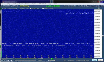
I want to see how raising the chip temperature to about 50 degrees C will affect frequency stability of the propeller chip. I decided that for my initial testing, I would just put the board under a halogen lamp and monitor the chip surface temperature with a laser thermometer.
After a few minutes the surface temperature has stabilized at about 55,4 C or 131,7 F.
I fired up my QRSS beacon code and gave it a bunch of text to send. The initial results results are not encouraging:
When I turn off the heat source, the expected drift back upwards begins. I saw more than a 150 Hz change in frequency from heat on (50C) to heat off (20C).
One thing I notice is that the crystal is removable and therefore there is considerable mechanical instability in the crystal socket and the associated change in circuit capacitance and resistance that goes along with these connections being able to move. I noticed that as the board heated up there were more small excursions in frequency as evidenced by the jitters in the waterfall display of the line than there are when the board is at room temperature where the jitters tend to disappear.

So, I supect there is not much I can conclude here other than I have an incredibly crude setup for this kind of testing. My intuition and the deep dive of the frequency with the heat on indicates to me that it is likely that whilst the surface temperature appeared to have stabilized, the internal temperature of the chip may not have yet stabilized. I need a proper environmental chamber that can maintain temperature tolerances more closely and need to give the device sufficient time to completely heat up. I also need to address the crystal socket issues as it appears to introduce a lot of instability as it heats up.
More head scratching whilst I figure out a better setup.
I decided to measure the propeller RF oscillator accuracy tonight. I find that my random sample of one Propeller Board to be accurate to 1 ppm over the range of 1 Mhz to 100 Mhz. In my case, the error is always negative requiring a positive offset to correct back to the proper frequency.
From this, I should be able to calculate an error offset for the oscillator over the entire frequency range once the error correction at any given frequency is known for the particular propeller board.
Drift on this particular board at 10 Mhz appears to be around 2 Hz over 2 minutes time, which represents a typical WSPR transmission. My next set of experiments with drift control will be to temperature stabilize the propeller chip at about 50 degrees C and see how this affects drift.
I had decided to build an all-band low-pass filter to use with my propeller projects and others. In adding up the costs and spending a little time looking around, I decided to purchase a great little kit from Virgil Stamps K5OOR down in Texas rather than roll my own. His low pass filter kit fit the bill exactly.
I am working on interfacing it to the propeller and plan to do band switching automatically based on the frequency chosen. This board will easily handle up to 100 watts of power. You can see plots of the filter response here.
After getting some much needed feedback on my keyer implementation, I have done several revisions to the keyer software, shortly to be posted on gitHub. Here is the current revision history list.
Revision History
----------------
Rev 1.1 - Thanks to Eldon, WA0UWH for pointing out a logic flaw in my
sendData method
Rev 1.2 - Updated to make into a proper object. Implemented get/put methods.
Rev 1.3 - Implemented Iambic A and Iambic B modes and one element memory.
Made Iambic B mode default
Rev 1.4 - Added bug mode (dits are automatic, dahs are not)
Added straight key mode (dit key input keys transmitter manually)
Added initPins(dit, dah, key, rf) to allow setting of pin assignments.
Defaults to 0, 1, 2, 27
Added public method swapPaddles to allow switching dit and dah paddles
I think the keyer is in pretty good shape now. I welcome any feedback on version 1.4 from anyone that may find it useful. Reminder that with the addition of proper low pass filters, this code functions as a full fledged CW transmitter for ham radio usage. Power output is approximately 5-7 mW putting it squarely in the QRP category. See my previous blog post for a simple amplifier to raise the output power sufficiently for beacon or CW operation.
Still trying to reclaim my shack from the clutches of ever expanding clutter. Managed to get the corner of one work table cleaned off and the microscope, hot air rework and soldering stations up and running.
I keep the LCR metre and signal tracer close at hand. Nice to have one place to do close work again. I cannot stress sufficiently my opinion that purchasing whatever equipment you need in order to be able to clearly see what you are doing is critical to your ability to enjoy electronics and ham radio hobbies.