I have updated my Minima code to support channelized 60 metre frequency allocations. If you select 60 metres through the band up/down buttons, the rotary encoder will now select the next/previous channel frequency and ensure that USB is set.
If on the other hand you tune the VFO to the 5Mhz frequency range without selecting 60 metres with the band switches, you may set any frequency you like or either sideband.
I do not yet support the CW+PSK 1.5 kHz offset from the normal SSB frequencies but plan to add this support soon.
I am pleased with how this is coming together. I am diverging a bit from the original Minima code, but intend to keep backwards compatibility as long as possible for those that are interested in that. I use conditional compile options to enable or disable functionality as desired. For example I can build for the original 6 wire LCD displays (16x2 or 20x4), for I2C displays of the same geometry as the 6 wire displays or for OLED displays. I can build for the original pot tuning or for a rotary encoder. I have a special build for Freetronics versions of the Arduino LCD shield. I can also build to support displays that have no notion of a display cursor.
Eventually however, my build will fork completely and become specialized to my needs/desires. I will maintain the last compatible build as a separate fork from Eldon, WA0UWH's fine work.
My code will soon be available from my github to anyone that would benefit from these changes.
Tuesday, July 29, 2014
Monday, July 28, 2014
Minima controller breadboard
I spent a little time this evening customizing the Minima controller code a little for my little OLED display. I will be bringing my breadboard to the pQRP pie and coffee evening this week on Wednesday for people to poke at and give some feedback. Come join us at Bob's Brew and Burgers in Everett at 19:00, grab a burger and visit.
Sunday, July 27, 2014
Minima breadboard of Controller
I have integrated my keyer code that was originally developed for the Propeller hardware and ported to the Arduino with the Minima firmware. My Si570 driver enabling 1 Hz tuning, AdaFruit's encoder driver and my latest OLED display have all been integrated with the Minima firmware.


The lash-up I have for tested can be seen below. This implements a working Minima controller with rotary encoder tuning and an OLED display. The keyer paddles and sidetone speaker are enabled by the freeing up of LCD display pins by converting the display to I2C.
Rather than build a controller board, I am laying out an Arduino shield board that will contain the Minima's Si570 and connectors for all the other components such as the encoder, display, CW speed control, paddles, PTT and a myriad of buttons. I have adopted the button logic pioneered by Eldon, WA0UWH. The shield will contain solder pads for an optional second Si570 that could be used for a BFO signal, easily set to be optimum for USB, LSB or CW. Both Si570 devices will have solder pads for a resistive pad to allow easy setting of output level down from the 13 dbm of the Si570. This would allow experimenting with different mixers for example. If no attenuation is desired, a 0 ohm resistor or solder jumper may be installed instead. This also allows for a load resistor to be installed if desired. Here is a quick screenshot of my current (incomplete) state of things:
I am also laying out a PCB for the Minima transceiver module. I have gone back and forth on making it SMT or thru-hole and have decided to use SMT as much as possible. Some of the components will need be thru-hole, but to the degree possible, I will use SMT components. My build will be pretty generic, though I am contemplating using a different crystal filter as I have a module that has been rattling around in my junque box for a number of years that might be fun to use rather than the discrete crystal filter of the Minima. If I do use the filter module, I will attempt to lay it out such that it could be built either way.
Meanwhile, I am collecting parts for the build.
Sunday, July 20, 2014
MicroLCD issues
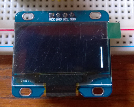
I have just started investigating why both of my new OLED displays require a 2 pixel offset to the right in order to prevent truncating the display. Starting out easy, we go with the simplest bit of code to turn on the LCD.
#include <Wire.h>
#include <MicroLCD.h>
LCD_SSD1306 lcd;
void setup()
{
lcd.begin();
}
void loop()
{
// put your main code here, to run repeatedly:
}
This code results in the following display. Notice the white bar on the right side. The display clear code is already suspect. Unplugging the display and re-running the code moves the white bar to the left side of the display running the entire way from top to bottom.
This is the code in the LCD initialization function that clears the display.
ssd1306_command(SSD1306_SETLOWCOLUMN | 0x0); // low col = 0
ssd1306_command(SSD1306_SETHIGHCOLUMN | 0x0); // hi col = 0
ssd1306_command(SSD1306_SETSTARTLINE | 0x0); // line #0
for (byte i = 0; i < SSD1306_LCDHEIGHT / 8; i++) {
// send a bunch of data in one xmission
ssd1306_command(0xB0 + i);//set page address
ssd1306_command(0);//set lower column address
ssd1306_command(0x10);//set higher column address
for(byte j = 0; j < 8; j++){
Wire.beginTransmission(_i2caddr);
Wire.write(0x40);
for (byte k = 0; k < SSD1306_LCDWIDTH / 8; k++) {
Wire.write(0);
}
Wire.endTransmission();
}
}
If I change k < SSD1306_LCDWIDTH to k <= SSD1306_LCDWIDTH then I can get the entire display to clear. However, this is suspect because as written, it should work logically speaking.
When the device is initialized, if no cursor setting operations are performed, the first text will be displayed in the lower left corner without any truncation. Once any cursor setting is done, The truncation is present from that point forward.
I will dig into the driver further, but for now I have fixed this by moving the inter-character spacing to the front of a character rather than the end and additionally provide two additional inter-character spaces at the beginning of a line of text.
#include <Wire.h>
#include <MicroLCD.h>
LCD_SSD1306 lcd;
uint8_t invert = 0;
void setup()
{
lcd.begin();
lcd.clear();
for (int i = 0; i < 8; i++)
{
lcd.print("A");
lcd.print(i);
lcd.print("-----------------");
lcd.print(i);
lcd.println("B");
}
}
loop()
{
}
The code above now displays correctly with no truncation. This provides for 21 colums by 8 rows of text using the 5x8 font. When I have time to dig into this further, I will post further updates on this topic.

#include <Wire.h>
#include <MicroLCD.h>
LCD_SSD1306 lcd;
void setup()
{
lcd.begin();
}
void loop()
{
// put your main code here, to run repeatedly:
}
This code results in the following display. Notice the white bar on the right side. The display clear code is already suspect. Unplugging the display and re-running the code moves the white bar to the left side of the display running the entire way from top to bottom.
This is the code in the LCD initialization function that clears the display.
ssd1306_command(SSD1306_SETLOWCOLUMN | 0x0); // low col = 0
ssd1306_command(SSD1306_SETHIGHCOLUMN | 0x0); // hi col = 0
ssd1306_command(SSD1306_SETSTARTLINE | 0x0); // line #0
for (byte i = 0; i < SSD1306_LCDHEIGHT / 8; i++) {
// send a bunch of data in one xmission
ssd1306_command(0xB0 + i);//set page address
ssd1306_command(0);//set lower column address
ssd1306_command(0x10);//set higher column address
for(byte j = 0; j < 8; j++){
Wire.beginTransmission(_i2caddr);
Wire.write(0x40);
for (byte k = 0; k < SSD1306_LCDWIDTH / 8; k++) {
Wire.write(0);
}
Wire.endTransmission();
}
}
If I change k < SSD1306_LCDWIDTH to k <= SSD1306_LCDWIDTH then I can get the entire display to clear. However, this is suspect because as written, it should work logically speaking.
When the device is initialized, if no cursor setting operations are performed, the first text will be displayed in the lower left corner without any truncation. Once any cursor setting is done, The truncation is present from that point forward.
I will dig into the driver further, but for now I have fixed this by moving the inter-character spacing to the front of a character rather than the end and additionally provide two additional inter-character spaces at the beginning of a line of text.
#include <Wire.h>
#include <MicroLCD.h>
LCD_SSD1306 lcd;
uint8_t invert = 0;
void setup()
{
lcd.begin();
lcd.clear();
for (int i = 0; i < 8; i++)
{
lcd.print("A");
lcd.print(i);
lcd.print("-----------------");
lcd.print(i);
lcd.println("B");
}
}
loop()
{
}
The code above now displays correctly with no truncation. This provides for 21 colums by 8 rows of text using the 5x8 font. When I have time to dig into this further, I will post further updates on this topic.
Saturday, July 19, 2014
New LCD display
I have just received a couple of nice little display modules from China. These cute little devices are I2C interfaced and use the MicroLCD Arduino library for the SSD1306 controller. http://freematics.com/store
The displays are relatively cheap in single unit quantities of USD9.95. Two of them and 90g shipping delivered for USD24.85. Shipping took 12 days.
The device is a 3.3 volt device and interfaces nicely with the Arduino if you remember that you don't want to use the internal pull-up resistors and instead use external resistors to a 3.3 volt rail.
The display comes in two relatively small formats 0.9" and 1.3". Since it is an OLED display, the direct sunshine readability is excellent.
Since I have converted my Minima code to use I2C displays, I decided to hook it up and modify the Minima code as necessary to utilize this display. The result is as you can see below.
As is the case with most things I buy from China, there are a couple of anomalies that I have noted...
1. The first two pixel columns are not visible on the display. By offsetting two pixels to the right, the result is what you see above.
2. There is no cursor support in the shipped library (MicroLCD) so some investigation will be necessary to see how to implement similar functionality.
This should be fun for a number of projects, nice and compact and easy to interface, anomalies and all...
Here I have increased the font size for my tired eyes. I think it still looks pretty good.
Tuesday, July 15, 2014
Minima hardware build
I have spent some time today organizing my Minima hardware so that it is not quite so fragile and breadboard-ish in preparation for starting to put together my own rig.
I am comfortable that I have the software in good shape and it is time to think about pulling together my own build.
Here is what I have for a front panel. There is a 20 column by 4 line display, three push-buttons and a rotary encoder. Readers of my blog may recognize this as the panel for my beacon project which is being re-purposed for this project.

I have mounted an I2C daughter board on the LCD in order to reduce the number of pins required to support the LCD. I am not going to use the plethora of buttons I have seen on other designs. I am also using a commercially available Arduino Uno board rather than build a controller board. I have mounted it on the back of the LCD. The remainder of the electronics of the radio will be in the bottom of the box.

I am replacing the potentiometer tuning with a rotary encoder and adding my iambic keyer code to the main Minima sketch. If sufficient flash is available, I will also add my Arduino beacon code to the mix. This may require an ATMega2560 device with its larger flash and RAM. There may be sufficient space, but RAM in particular is getting a bit tight.
I am comfortable that I have the software in good shape and it is time to think about pulling together my own build.
Here is what I have for a front panel. There is a 20 column by 4 line display, three push-buttons and a rotary encoder. Readers of my blog may recognize this as the panel for my beacon project which is being re-purposed for this project.
I am replacing the potentiometer tuning with a rotary encoder and adding my iambic keyer code to the main Minima sketch. If sufficient flash is available, I will also add my Arduino beacon code to the mix. This may require an ATMega2560 device with its larger flash and RAM. There may be sufficient space, but RAM in particular is getting a bit tight.
Wednesday, July 9, 2014
Salmoncon Presentation
This weekend I will speaking briefly on my recent code changes to the Minima code base to enable 1Hz tuning on the Minima transceiver at Salmoncon this weekend. Salmoncon 2014 is this weekend at Valley Camp in North Bend area of the Cascade Mountains. It is a beautiful venue and a great opportunity to hang out with other hams for the weekend. Look for us on the air using the special event call sign of K7S or better yet, come out and join us.
Subscribe to:
Posts (Atom)