I have completed (as far as I went) the build of my Minima Controller Shield, but have yet to complete testing of the board. I populated only a single Si570, the edge and ICSP stackable headers and the header for my OLED display.
The prototype board needs a little work. I need to move the VFO SMA edge connector away from the USB connector. This will work for a prototype, but needs to move in the final version for sure.
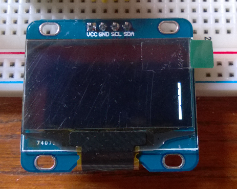
The OLED display is a 3V3 device and I have it sharing the same I2C bus as the first Si570 for the VFO. There is also a 5V set of connections for an LCD display with an I2C backpack for example. This shares the same I2C bus as the PCA9546 multiplexer input, so it should allow 5V displays to work without driver modifications. I will need to customize the 3V3 OLED driver to take into account that it is connected to the PCA9546 multiplexer. I used this device because it allows voltage level conversion with a 5V input side and four 1.8 - 5V or more output side I2C buses. It also allows me to address multiple devices that do not allow you to change their I2C address such as the Si570. Without it, one would be limited to a single Si570 on a bus.
Ok, off to do some voltage testing and then to see if I can address the PCA9546. If so, I will get busy on my display driver changes and testing the Si570. I plan to roll my changes back into my Si570 driver to allow multiple instances behind a multiplexer as a compile time option.
Showing posts with label OLED. Show all posts
Saturday, September 6, 2014
Sunday, July 20, 2014
MicroLCD issues
I have just started investigating why both of my new OLED displays require a 2 pixel offset to the right in order to prevent truncating the display. Starting out easy, we go with the simplest bit of code to turn on the LCD.
#include <Wire.h>
#include <MicroLCD.h>
LCD_SSD1306 lcd;
void setup()
{
lcd.begin();
}
void loop()
{
// put your main code here, to run repeatedly:
}
This code results in the following display. Notice the white bar on the right side. The display clear code is already suspect. Unplugging the display and re-running the code moves the white bar to the left side of the display running the entire way from top to bottom.
This is the code in the LCD initialization function that clears the display.
ssd1306_command(SSD1306_SETLOWCOLUMN | 0x0); // low col = 0
ssd1306_command(SSD1306_SETHIGHCOLUMN | 0x0); // hi col = 0
ssd1306_command(SSD1306_SETSTARTLINE | 0x0); // line #0
for (byte i = 0; i < SSD1306_LCDHEIGHT / 8; i++) {
// send a bunch of data in one xmission
ssd1306_command(0xB0 + i);//set page address
ssd1306_command(0);//set lower column address
ssd1306_command(0x10);//set higher column address
for(byte j = 0; j < 8; j++){
Wire.beginTransmission(_i2caddr);
Wire.write(0x40);
for (byte k = 0; k < SSD1306_LCDWIDTH / 8; k++) {
Wire.write(0);
}
Wire.endTransmission();
}
}
If I change k < SSD1306_LCDWIDTH to k <= SSD1306_LCDWIDTH then I can get the entire display to clear. However, this is suspect because as written, it should work logically speaking.
When the device is initialized, if no cursor setting operations are performed, the first text will be displayed in the lower left corner without any truncation. Once any cursor setting is done, The truncation is present from that point forward.
I will dig into the driver further, but for now I have fixed this by moving the inter-character spacing to the front of a character rather than the end and additionally provide two additional inter-character spaces at the beginning of a line of text.
#include <Wire.h>
#include <MicroLCD.h>
LCD_SSD1306 lcd;
uint8_t invert = 0;
void setup()
{
lcd.begin();
lcd.clear();
for (int i = 0; i < 8; i++)
{
lcd.print("A");
lcd.print(i);
lcd.print("-----------------");
lcd.print(i);
lcd.println("B");
}
}
loop()
{
}
The code above now displays correctly with no truncation. This provides for 21 colums by 8 rows of text using the 5x8 font. When I have time to dig into this further, I will post further updates on this topic.
#include <Wire.h>
#include <MicroLCD.h>
LCD_SSD1306 lcd;
void setup()
{
lcd.begin();
}
void loop()
{
// put your main code here, to run repeatedly:
}
This code results in the following display. Notice the white bar on the right side. The display clear code is already suspect. Unplugging the display and re-running the code moves the white bar to the left side of the display running the entire way from top to bottom.
This is the code in the LCD initialization function that clears the display.
ssd1306_command(SSD1306_SETLOWCOLUMN | 0x0); // low col = 0
ssd1306_command(SSD1306_SETHIGHCOLUMN | 0x0); // hi col = 0
ssd1306_command(SSD1306_SETSTARTLINE | 0x0); // line #0
for (byte i = 0; i < SSD1306_LCDHEIGHT / 8; i++) {
// send a bunch of data in one xmission
ssd1306_command(0xB0 + i);//set page address
ssd1306_command(0);//set lower column address
ssd1306_command(0x10);//set higher column address
for(byte j = 0; j < 8; j++){
Wire.beginTransmission(_i2caddr);
Wire.write(0x40);
for (byte k = 0; k < SSD1306_LCDWIDTH / 8; k++) {
Wire.write(0);
}
Wire.endTransmission();
}
}
If I change k < SSD1306_LCDWIDTH to k <= SSD1306_LCDWIDTH then I can get the entire display to clear. However, this is suspect because as written, it should work logically speaking.
When the device is initialized, if no cursor setting operations are performed, the first text will be displayed in the lower left corner without any truncation. Once any cursor setting is done, The truncation is present from that point forward.
I will dig into the driver further, but for now I have fixed this by moving the inter-character spacing to the front of a character rather than the end and additionally provide two additional inter-character spaces at the beginning of a line of text.
#include <Wire.h>
#include <MicroLCD.h>
LCD_SSD1306 lcd;
uint8_t invert = 0;
void setup()
{
lcd.begin();
lcd.clear();
for (int i = 0; i < 8; i++)
{
lcd.print("A");
lcd.print(i);
lcd.print("-----------------");
lcd.print(i);
lcd.println("B");
}
}
loop()
{
}
The code above now displays correctly with no truncation. This provides for 21 colums by 8 rows of text using the 5x8 font. When I have time to dig into this further, I will post further updates on this topic.
Saturday, July 19, 2014
New LCD display
I have just received a couple of nice little display modules from China. These cute little devices are I2C interfaced and use the MicroLCD Arduino library for the SSD1306 controller. http://freematics.com/store
The displays are relatively cheap in single unit quantities of USD9.95. Two of them and 90g shipping delivered for USD24.85. Shipping took 12 days.
The device is a 3.3 volt device and interfaces nicely with the Arduino if you remember that you don't want to use the internal pull-up resistors and instead use external resistors to a 3.3 volt rail.
The display comes in two relatively small formats 0.9" and 1.3". Since it is an OLED display, the direct sunshine readability is excellent.
Since I have converted my Minima code to use I2C displays, I decided to hook it up and modify the Minima code as necessary to utilize this display. The result is as you can see below.
As is the case with most things I buy from China, there are a couple of anomalies that I have noted...
1. The first two pixel columns are not visible on the display. By offsetting two pixels to the right, the result is what you see above.
2. There is no cursor support in the shipped library (MicroLCD) so some investigation will be necessary to see how to implement similar functionality.
This should be fun for a number of projects, nice and compact and easy to interface, anomalies and all...
Here I have increased the font size for my tired eyes. I think it still looks pretty good.
Subscribe to:
Posts (Atom)