Today I accepted a Firmware Engineer position with LOUD Technologies in Woodinville, WA working with the Mackie Digital Audio Mixing team. I will be starting mid-July, so my job hunt status appears to be over. Yay! Check out their web site when you get a chance. http://loudtechinc.com/
Thursday, June 25, 2015
Wednesday, June 3, 2015
Diode Ring Mixer - UPDATED
In an attempt to firstly melt more solder than I have of late, and secondly to try and actually understand the operation of a mixer, I have decided to build one up from discrete components, including (gasp) winding my own transformers.
The rather rough diagramme of the circuit I propose to build looks something like this which is based on the fine design by Pete Juliano N6QW found here:

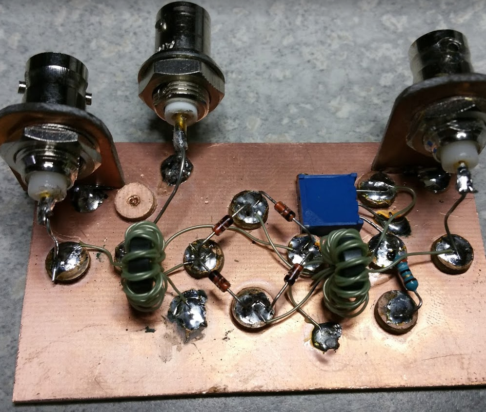
I found a few 1N6263 Schottky diodes in my junk box and out of the lot was able to find four that matched on the forward voltage drop to the millivolt level at 0V300. A quick look around found a bit of PCB and a 1/4 inch sheet metal hole punch allowed me to create simple Manhattan pads. Here is the layout at the start of the build with just the diodes installed.

I wound coils on FT37-43 cores. I seem to be out of enameled wire, so I am going to try this with 30 gauge insulated wire-wrap wire as the number of turns is small, though the coils are trifilar. I wound the trfilar wires together using a drill motor and then wound the three wires onto the core. Ten turns, both coils are identical.
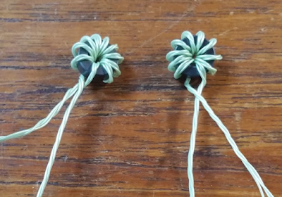
Separating the coil winding ends, I check continuity on them and mark them with a Sharpie (why is a dull felt pen called a Sharpie?) on each end of the wire with no mark, a single mark or a double mark. The no mark wire will be the single coil while the one and two mark wires will be hooked in series (observing phasing). The left side as drawn in the circuit above, will have a 100 ohm variable resistor at the centre tap of the transformer secondary to allow small balance adjustments. As suggested by Pete Juliano N6QW, but not drawn above, I plan to also include a 39 ohm resistor that is switchable to ground from the centre tap in order to intentionally unbalance the mixer. This is useful for injecting carrier for tune-up purposes for example.
The final build, minus the output filter can be seen below. I hope to get out of interview preparation mode soon so that I can have some time to check this out. The trim pot is a 100 ohm multi-turn pot to allow fine tuning of the balance. Connecting the top of the 39 ohm resistor to ground will deliberately unbalance the mixer.

Finally got a chance to see if this little guy is mixing or not. I set the 100 ohm multi-turn pot to the middle and attached the output of a 20 MHz crystal oscillator to it along with a signal generator output and had a look at the output on the spectrum analyzer. Firstly, we needed some connectors.


The rather rough diagramme of the circuit I propose to build looks something like this which is based on the fine design by Pete Juliano N6QW found here:

I found a few 1N6263 Schottky diodes in my junk box and out of the lot was able to find four that matched on the forward voltage drop to the millivolt level at 0V300. A quick look around found a bit of PCB and a 1/4 inch sheet metal hole punch allowed me to create simple Manhattan pads. Here is the layout at the start of the build with just the diodes installed.

I wound coils on FT37-43 cores. I seem to be out of enameled wire, so I am going to try this with 30 gauge insulated wire-wrap wire as the number of turns is small, though the coils are trifilar. I wound the trfilar wires together using a drill motor and then wound the three wires onto the core. Ten turns, both coils are identical.

Separating the coil winding ends, I check continuity on them and mark them with a Sharpie (why is a dull felt pen called a Sharpie?) on each end of the wire with no mark, a single mark or a double mark. The no mark wire will be the single coil while the one and two mark wires will be hooked in series (observing phasing). The left side as drawn in the circuit above, will have a 100 ohm variable resistor at the centre tap of the transformer secondary to allow small balance adjustments. As suggested by Pete Juliano N6QW, but not drawn above, I plan to also include a 39 ohm resistor that is switchable to ground from the centre tap in order to intentionally unbalance the mixer. This is useful for injecting carrier for tune-up purposes for example.
The final build, minus the output filter can be seen below. I hope to get out of interview preparation mode soon so that I can have some time to check this out. The trim pot is a 100 ohm multi-turn pot to allow fine tuning of the balance. Connecting the top of the 39 ohm resistor to ground will deliberately unbalance the mixer.

Finally got a chance to see if this little guy is mixing or not. I set the 100 ohm multi-turn pot to the middle and attached the output of a 20 MHz crystal oscillator to it along with a signal generator output and had a look at the output on the spectrum analyzer. Firstly, we needed some connectors.
I gave it 20 MHz on one port, 1 MHz on the other, both at 7 dBm and obtained the following output. Both the sum and difference were within 0.08 dBm of each other.
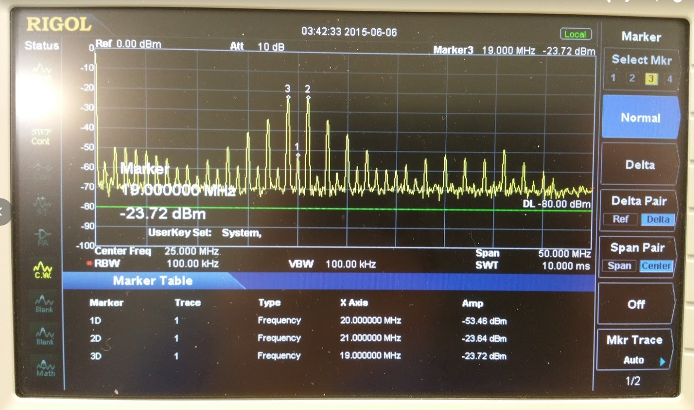
So, we seem to be mixing and with proper IF filtering following, should be good to go. Many thanks to Wayne NB6M for helping with the testing.
Subscribe to:
Posts (Atom)