Showing posts with label I2C. Show all posts

Monday, May 11, 2015

i2c Scanner

I wanted to share a useful script that I have written to determine the available addresses on Arduino's i2c (pronounced "eye-squared-see") bus.  When attaching new hardware where you may not have the address for the device available, this script can be useful to determine that information.  It is also useful for debugging connectivity issues on an i2c bus.

To use, connect your hardware to the bus clock and data lines.  Apply power and ground your hardware as well.  Run this script and open the serial monitor at 115200 baud.  You can change this speed to suit your preferences.  The serial monitor window will list all of the device addresses found on the bus.

As always, if you need assistance, please let me know by dropping me a note at ko7m at arrl dot net or by posting here and I will try to help you out.

// i2c_scanner
//

#include <Wire.h>

void setup()
{
  Wire.begin();

  Serial.begin(115200);
  Serial.println("i2c Scanner");
}

void printAddress(byte address)
{
  if (address<16) Serial.print("0");
  Serial.println(address, HEX);
}

void loop()
{
  

    Serial.println("Scanning...");
  
    int nDevices = 0;
    
    for(int address = 1; address < 127; address++ ) 
    {
      Wire.beginTransmission(address);
      int error = Wire.endTransmission();
      
      // Just for good measure, try again
      if (error != 0)
      {
//        Serial.print("Error ");
//        Serial.println(error, DEC);
//        Serial.println("Retrying...");
        delay(10);
        Wire.beginTransmission(address);
        error = Wire.endTransmission();
      }
  
      if (error == 0)
      {
        Serial.print("i2c device found at address 0x");
        printAddress(address);  
        nDevices++;
      }
      else if (error == 4) 
      {
        Serial.print("Unknown error at address 0x");
        printAddress(address);
      }    
    }
    if (nDevices == 0)
      Serial.println("No i2c devices found\n");
    else
      Serial.println("");

  // Hang the script
  while (1==1);
}

Thursday, November 6, 2014

New Minima-like build

My good friend Wayne NB6M has kindly loaned me his Minima-like build using my controller shield for the Arduino.  His front panel is very similar to his original Minima build, but is now sporting a 20x4 display.  He has removed the reset button from the front panel and added input for paddles in anticipation of me actually finishing the integration of my keyer code to the Minima code base.


Looking at the back of the panel, we can see the Arduino Uno and my controller shield mounted on the back of the display board.  Wayne has used #12 bare copper wire soldered to the front panel to provide attach points for the Uno and shield.  My shield will be modified to provide through-hole plating and solder pads so that it can be soldered in place.

The display board has been converted to i2c with a backpack board and the rotary encoder uses pins freed up by display being converted to i2c.  The current shield design does not incorporate the proposed pins for the encoder from the discussion list, but will be modified in the final run to be compliant.


Wayne is using a pretty conventional IF strip from the Minima, but has chosen to replace the KISS mixer and BFO mixer with ADE-1 devices.  His audio section is from a pre-existing project re-purposed for this project.  The two SMA connectors connect to the VFO and BFO Si570 outputs from my controller shield.  No low pass filter sections yet.  The current configuration makes a pretty nice general coverage receiver.


I have handed off Wayne's other Minima build to Eldon so he will have a working radio to test with during his software development efforts.

Tuesday, September 9, 2014

Minima Controller - 5V i2c LCD support

I have tested my Minima controller successfully for support of 16x2 or 20x4 LCD displays using a 5V i2c backpack.  Here is a 20x4 display running my changes to WA0UWH's latest firmware for Minima.


Only two wires plus power and ground required to support these displays.  The code is conditionally compiled with or without i2c display support as desired with the default to continue to support 6 wire displays.  Converting to an i2c display will be required in order to free up I/O pins to support such things as rotary controllers, keyer paddles, etc.  This change however will continue to work by default with the original Minima hardware configuration for the LCD display.  In order to enable the functionality, please uncomment the following line near the top of the file "radiono.ino".

    #define USE_I2C_LCD 1

  You will also need to obtain the i2c library LiquidTWI and install in your Arduino environment in order to build with this support.

It should be noted that my Minima Controller shield is not required to support i2c displays.

Please contact me directly by email at ko7m at arrl.net or by commenting on this post if you have any problems and I will do my best to assist.

Minima Controller - OLED Display

After some initial head scratching, I have my adaptation of the Minima sketch that supports my OLED display up and running on my controller shield.


I was initially not getting any joy out of the OLED display and it remained black despite my efforts.  However, I had stupidly placed the initialization of the PCA9546 multiplexer after the initialization of the OLED display.  Since the OLED cannot be addressed until the mux is set to channel 1, no joy.

I did write a somewhat useful utility that enumerates all i2c device id's that can be seen on the Arduino i2c bus as well as on each of the four channels of the mux which others may find useful.

Debugging this did point out to me an error in my PCA9546 code and a couple of changes I would like to make.

1. I have mistakenly made the selectChannel() method private, when it should be public.
2. The channel argument to selectChannel() is currently a bit field.  The bottom 4 bits indicate which of the four channels should be enabled.  I believe I will change this to just take a channel number rather than a bit field.  I also need a way to deselect all channels.
3. I need to provide a constructor for the PCA9546 class that will allow initialization without selecting any channel.

I will provide an updated listing of PCA9546 class with these changes in a separate post.

Here is the code for scanning for devices connected to the i2c bus and all channels of the PCA9546.

// i2c_scanner
//

#include <Wire.h>
#include "PCA9546.h"

PCA9546 *mux;
char buf[66];

void setup()
{
  Wire.begin();

  Serial.begin(115200);
  Serial.println("i2c Scanner");
  mux = NULL;
}

void printAddress(byte address)
{
  if (address<16) Serial.print("0");
  Serial.println(address, HEX);
}

void loop()
{
  uint8_t nChannel;
  
  for (nChannel = 0; nChannel <= 4; nChannel++)
  {
    Serial.print("Channel ");
    Serial.println(nChannel, DEC);
    byte error, address;
    int nDevices;
  
    Serial.println("Scanning...");
  
    nDevices = 0;
    if (nChannel > 0)
    {
      if (mux == NULL)
      {
        mux = new PCA9546(0x70, 1 << (nChannel - 1));
      }
      else
      {
        bool fRc = mux->selectChannel(1 << (nChannel - 1));
      }
    }
    
    for(address = 1; address < 127; address++ ) 
    {
      Wire.beginTransmission(address);
      error = Wire.endTransmission();
      
      // Just for good measure, try again
      if (error != 0)
      {
        delay(10);
        Wire.beginTransmission(address);
        error = Wire.endTransmission();
      }
  
      if (error == 0)
      {
        Serial.print("i2c device found at address 0x");
        printAddress(address);  
        nDevices++;
      }
      else if (error == 4) 
      {
        Serial.print("Unknown error at address 0x");
        printAddress(address);
      }    
    }
    if (nDevices == 0)
      Serial.println("No i2c devices found\n");
    else
      Serial.println("");
  }

  // Hang the script
  while (1==1);
}

Sunday, July 20, 2014

MicroLCD issues

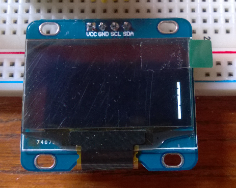
I have just started investigating why both of my new OLED displays require a 2 pixel offset to the right in order to prevent truncating the display.  Starting out easy, we go with the simplest bit of code to turn on the LCD.

#include <Wire.h>
#include <MicroLCD.h>

LCD_SSD1306 lcd;

void setup()
{
  lcd.begin();
}

void loop()
{
  // put your main code here, to run repeatedly:

}

This code results in the following display.  Notice the white bar on the right side.  The display clear code is already suspect.  Unplugging the display and re-running the code moves the white bar to the left side of the display running the entire way from top to bottom.


This is the code in the LCD initialization function that clears the display.

    ssd1306_command(SSD1306_SETLOWCOLUMN | 0x0);  // low col = 0
    ssd1306_command(SSD1306_SETHIGHCOLUMN | 0x0); // hi col = 0
    ssd1306_command(SSD1306_SETSTARTLINE | 0x0);  // line #0

    for (byte i = 0; i < SSD1306_LCDHEIGHT / 8; i++) {
      // send a bunch of data in one xmission
        ssd1306_command(0xB0 + i);//set page address
        ssd1306_command(0);//set lower column address
        ssd1306_command(0x10);//set higher column address

        for(byte j = 0; j < 8; j++){
            Wire.beginTransmission(_i2caddr);
            Wire.write(0x40);
            for (byte k = 0; k < SSD1306_LCDWIDTH / 8; k++) {
                Wire.write(0);
            }
            Wire.endTransmission();
        }

    }

If I change k < SSD1306_LCDWIDTH to k <= SSD1306_LCDWIDTH then I can get the entire display to clear.  However, this is suspect because as written, it should work logically speaking.

When the device is initialized, if no cursor setting operations are performed, the first text will be displayed in the lower left corner without any truncation.  Once any cursor setting is done, The truncation is present from that point forward.

I will dig into the driver further, but for now I have fixed this by moving the inter-character spacing to the front of a character rather than the end and additionally provide two additional inter-character spaces at the beginning of a line of text.

#include <Wire.h>
#include <MicroLCD.h>


LCD_SSD1306 lcd;
uint8_t invert = 0;

void setup()
{
  lcd.begin();
  lcd.clear();
  for (int i = 0; i < 8; i++)
  {
    lcd.print("A");
    lcd.print(i);
    lcd.print("-----------------");
    lcd.print(i);
    lcd.println("B");
  }

}

loop()
{
}

The code above now displays correctly with no truncation.  This provides for 21 colums by 8 rows of text using the 5x8 font.  When I have time to dig into this further, I will post further updates on this topic.


Saturday, July 19, 2014

New LCD display

I have just received a couple of nice little display modules from China.  These cute little devices are I2C interfaced and use the MicroLCD Arduino library for the SSD1306 controller.  http://freematics.com/store
 
The displays are relatively cheap in single unit quantities of USD9.95.  Two of them and 90g shipping delivered for USD24.85.  Shipping took 12 days.

The device is a 3.3 volt device and interfaces nicely with the Arduino if you remember that you don't want to use the internal pull-up resistors and instead use external resistors to a 3.3 volt rail.

The display comes in two relatively small formats 0.9" and 1.3".  Since it is an OLED display, the direct sunshine readability is excellent.

Since I have converted my Minima code to use I2C displays, I decided to hook it up and modify the Minima code as necessary to utilize this display.  The result is as you can see below.


As is the case with most things I buy from China, there are a couple of anomalies that I have noted...

1. The first two pixel columns are not visible on the display.  By offsetting two pixels to the right, the result is what you see above.

2. There is no cursor support in the shipped library (MicroLCD) so some investigation will be necessary to see how to implement similar functionality.

This should be fun for a number of projects, nice and compact and easy to interface, anomalies and all... 

Here I have increased the font size for my tired eyes.  I think it still looks pretty good.


Tuesday, July 15, 2014

Minima hardware build

I have spent some time today organizing my Minima hardware so that it is not quite so fragile and breadboard-ish in preparation for starting to put together my own rig.

I am comfortable that I have the software in good shape and it is time to think about pulling together my own build.

Here is what I have for a front panel.  There is a 20 column by 4 line display, three push-buttons and a rotary encoder.  Readers of my blog may recognize this as the panel for my beacon project which is being re-purposed for this project.


I have mounted an I2C daughter board on the LCD in order to reduce the number of pins required to support the LCD.  I am not going to use the plethora of buttons I have seen on other designs.  I am also using a commercially available Arduino Uno board rather than build a controller board.  I have mounted it on the back of the LCD.  The remainder of the electronics of the radio will be in the bottom of the box.


I am replacing the potentiometer tuning with a rotary encoder and adding my iambic keyer code to the main Minima sketch.  If sufficient flash is available, I will also add my Arduino beacon code to the mix.  This may require an ATMega2560 device with its larger flash and RAM.  There may be sufficient space, but RAM in particular is getting a bit tight.

Monday, February 27, 2012

Rotary Encoders on Propeller

This evening, I have been playing with Eldon's code to handle rotary encoders.  Works nicely as long as the encoder inputs to the propeller have pull-up resistors and a capacitor to ground to make a little integrator.  Helps with debouncing the encoder output.

So far the LCD driver is working nicely for both I2C displays and parallel displays.  Eldon seems to have switched over to using mine.

I will next work up some code to use the encoder for frequency selection.  Everyone else is well beyond this point, but I have focused mostly on the WSPR encoder solution whilst everyone has been continuing on with UI and other concerns.  I will catch up here soon...

Thursday, February 23, 2012

Propeller LCD and RTC work

Sorry for no updates for a while as I have been ill unfortunately.  Starting to feel better now however so I am back playing around with propeller.  I have a DS1307 real-time clock module (RTC) and the I2C LCD module from my Arduino beacon project that I have been wanting to get working.

The RTC was a complete no-brainer, it just works.  I plan to use it to allow atonomous operation of my beacons that need accurate time information such as WSPR.

The LCD however was a bit of a problem as I am not happy with the display drivers that are out there and have not found an acceptable I2C implementation for any display that I care for.

So, I ported the driver I was using for Arduino to spin and have it working now at least at a macro level.  I have not tested the functionality fully yet.  I am quite pleased with the initial performance.


The plan is to make a rather comprehensive driver that will work with either I2C or parallel mode, though I only will be using I2C.  Above you can see it driving my 20 character by 4 line display.  The I2C bit is implemented in the driver via bit-banging.  This allows the driver to be independent of any other I2C library.  The SDA and SCL pins can be specified with the default to share the I2C pins with the EEPROM.

On other fronts I am putting together a low pass filter module that uses six relay selectable low pass filters for the HF Bands 160 - 10 metres.  10 bands are covered with 6 filters.  Attenuation in the stop band should exceed -40dB.  I anticipate using an 8 bit I2C I/O expander, six bits of which will be used select the appropriate filter for the following bands: 160, 80, 60/40, 30/20, 17/15, 12/10 metres.  I anticipate using the remaining bits for transmit/receive switching and antenna auto-tuner control.  More to come on this.

Monday, November 14, 2011

LCD Performance and UI decisions in the beacon project

The beacon project is back on the front burner.  Frankly, one of the reasons that it has been stalled so long is because of the lousy UI performance.  The rotary encoder triggers an interrupt so I never lose control turns.  However, the display updates are very laggy and the amount of lag varies considerably.  I *HATE* laggy UIs and until now have not looked into why.  Frankly the I2C LiquidCrystal library was apparently a hasty adaptation of the original LCD library without regard to performance.  It was taking more than a dozen I2C commands for a single character to be updated, let alone the additional ones for cursor positioning and the like.  Bogus.  All bits are written simultaneously now and the lagginess is completely gone.  Sweet!  Many thanks to Kevin who pointed out the great work by falconfour in a comment to one of my previous posts.  Nice to be back on track and re-energized to complete this project.

I spent a lot of time talking to my pal Eldon about UI decisions.  I will be making some changes to the value setting library for alpha-numeric fields to see if the new paradigm works a little cleaner for non-numeric fields.

Another concept that we kicked around was the effect of TX percent on multi-band operation for WSPR.  Since WSPR frequencies have been cleanly defined for all bands, I am considering having TX percent of 100% mean the beacon will cycle through all bands on each two minute window.  A setup UI would be created to allow enable/disable of each of the bands.  See my previous post for a list of bands supported by this beacon (all up to and including 6 metres).  So, if you truely wanted to send 100% of the time on one band, you would have to disable all other bands as well as setting TX percent to 100%.  Otherwise, the beacon would sequence through the list of enabled bands every two minute window.  I am interested in feedback on this idea.  I think it makes sense to enable this multi-band mode only on TX percent = 100% as otherwise, i would have to completely rethink the meaning of TX percent when multiple bands are enabled.

Also regarding multi-band operation, I plan to make some concession for external low-pass filter selection based on the currently selected band or frequency.  Interested in feedback on what this might look like.  Some ideas:

  1. Provide the frequency to an external function that takes care of the magic itself and leave the details up to the implementer.
  2. Provide an enable bit (or a counter that is decoded by external hardware) that can be used trigger external relays to select an appropriate low pass filter which is set by one of the following:
    • The function described in #1 above as implemented by someone else.
    • Providing a set of configurable cutoff frequencies for the various external low-pass filters and automatically selecting one as appropriate based on frequency.
    • Define one filter per WSPR band and select based on frequency.  This is simple, but may be somewhat inappropriate as for example it makes little sense to have separate low pass filters for both 12 and 10 metres where one would suffice.
I have decided to replace my current rotary encoder with a different one from BI Technologies.  The Model EN11 rotary encoder is a nice, inexpensive (even in single unit quantities from Mouser) item that adds a push button and detents.  My current encoder had no detents and frankly, I prefer having them.  If desired, it can be ordered with or without the switch or the detents.  I will be using the switch to change the tuning rate rather than a separate push button.  See the datasheet here.  Thanks to Eldon for providing a sample of this encoder to me to try out with the beacon project.

Eldon and I also revisited the whole topic of what frequency to display on the LCD when in WSPR mode.  Most folks that use the great software by Joe Taylor are used to setting the rig display (on 30 metres for example) to 10.138700 MHz and generating tones in the 1400-1600 hz range to feed into your SSB transmitter.  The actual transmit frequency can be set by double clicking in the "waterfall" display or by typing it in to the "Tx:" frequency edit box.  One idea kicked around was to only display the WSPR band (30 metres, 20 metres, etc) and an offset from the start of the WSPR band.  The offset is only 200 hertz total.  This sort of makes sense to me, but I have an uneasyness when I don't know precisely what frequency I am transmitting on.  Joe Taylor's software shows the exact transmit frequency.  For example, if you clicked in the middle of the 30 metre band, it will show 14.140200 in the "Tx:" frequency box.  What is not clear to me is precisely what that frequency means since WSPR signals are composed of four separate tone frequencies that are separated by 1.4648 Hz.  In the absence of clarity from Joe's documentation, I have chosen to define the transmit frequency like this:


Each symbol is 1.4648 Hz apart and the displayed transmit frequency is mid-way between symbols 1 and 2.  Band edge operations need to take this into account if you wish to stay within the defined WSPR frequency range with the entire 6 Hz spectrum occupied by the complete WSPR signal.  Anyone have further thoughts or comments on this?

Anyway, it is nice to be back on track and making progress on my beacon again.

Thursday, March 24, 2011

I2C LCD performance

I am a bit disappointed in the performance of the Arduino LCD driver, especially with the I2C interface enabled.  I am not sure how much time I want to spend optimizing the standard Arduino libraries, especially since a beacon in operation really doesn't need a display.  Realistically, it is just convenient for me while developing this project.  I think what I will do is just optimize the display usage to only update what actually changes rather than repainting everything whenever anything changes.  If that is insufficient, I will turn off the frequently updated portions of the LCD when doing time critical operations such as when transmitting signals with critical timing criteria such as WSPR.