In a previous blog posting I have demonstrated an extremely simple transmitter / keyer implementation on the propeller platform. The next logical step was to build a receiver to go with it.
What I have implemented is a very simple direct conversion receiver based on the NE602 Gilbert Cell mixer and a LM386 audio amplifier. The circuit is based on the famous sudden receiver design from the Rev George Dobbs G3RJV many years ago and looks something like this:
My implementation removes all the tuned circuit stuff from pins 6 and 7 of the NE612 (NE602 in my circuit) and injects the RF generated by the propeller via a blocking capacitor directly into pin 6 to set the receive frequency.
Here is a photograph of the lash-up with the receiver built manhattan-style on a little 5x7 cm PCB scrap.
Right now I am sitting here listening to a 75 metre net running on 3.98 MHz LSB (The Oregon Emergency Net).
Obviously, I have a lot of work to do on user interface code...
Now as you might well imagine, there are a number of problems with playing at RF frequencies with bits of wire lashing all the bits and pieces together stuck into protoboards. For example, I had to move the RF pin as far from the encoder pins as I could in order to not confuse the encoder code. The frequency kept changing on its own until I turned off the RF. There is a fair amount of "hash" in the receiver audio being generated by the LCD controller chip. But as far as a proof-of-concept impelementation, I could not be happier.
With this success, I plan to put together a complete (simple) all-band transceiver using a propeller as the controller as well as RF generation component for both the transmitter oscillator as well as the local oscillator for the receiver.
This evening, I have been playing with Eldon's code to handle rotary encoders. Works nicely as long as the encoder inputs to the propeller have pull-up resistors and a capacitor to ground to make a little integrator. Helps with debouncing the encoder output.
So far the LCD driver is working nicely for both I2C displays and parallel displays. Eldon seems to have switched over to using mine.
I will next work up some code to use the encoder for frequency selection. Everyone else is well beyond this point, but I have focused mostly on the WSPR encoder solution whilst everyone has been continuing on with UI and other concerns. I will catch up here soon...
In a previous post, I mentioned that I was working on an I2C LCD driver. I have decided to support both I2C and parallel interfaces to common LCD displays that utilize the popular Hitachi HD44780 controller chip.
This work is largely completed at this point although there is some clean-up work to be done. One of the dilemmas I face is the question of how to implement cursor positioning. It is simple enough to envision an API that sets the cursor to some row/column pair, but should those rows and columns be zero-based or one-based values?
I have worked forever on systems wherein all such values are zero based. There does appear to be however some precident for using one-based values. For the moment, I have implemented two APIs, one that is zero-based and the other one-based. Perhaps that is an acceptable, albeit confusing solution.
I welcome any thoughts anyone might have on the topic.
I am waging war on the amount of clutter in my shack this weekend. It has gotten to where I could hardly get in the place. I have put the propeller beacon up on 30 metres on WSPR, QRSS and Opera. It runs on a 10 minute cycle, WSPR first, QRSS then Opera and then it waits for the end of the 10 minute cycle and repeats.
Let me know if you "hear" it on the air.
Sorry for no updates for a while as I have been ill unfortunately. Starting to feel better now however so I am back playing around with propeller. I have a DS1307 real-time clock module (RTC) and the I2C LCD module from my Arduino beacon project that I have been wanting to get working.
The RTC was a complete no-brainer, it just works. I plan to use it to allow atonomous operation of my beacons that need accurate time information such as WSPR.
The LCD however was a bit of a problem as I am not happy with the display drivers that are out there and have not found an acceptable I2C implementation for any display that I care for.
So, I ported the driver I was using for Arduino to spin and have it working now at least at a macro level. I have not tested the functionality fully yet. I am quite pleased with the initial performance.
The plan is to make a rather comprehensive driver that will work with either I2C or parallel mode, though I only will be using I2C. Above you can see it driving my 20 character by 4 line display. The I2C bit is implemented in the driver via bit-banging. This allows the driver to be independent of any other I2C library. The SDA and SCL pins can be specified with the default to share the I2C pins with the EEPROM.
On other fronts I am putting together a low pass filter module that uses six relay selectable low pass filters for the HF Bands 160 - 10 metres. 10 bands are covered with 6 filters. Attenuation in the stop band should exceed -40dB. I anticipate using an 8 bit I2C I/O expander, six bits of which will be used select the appropriate filter for the following bands: 160, 80, 60/40, 30/20, 17/15, 12/10 metres. I anticipate using the remaining bits for transmit/receive switching and antenna auto-tuner control. More to come on this.
In my previous post about my Propeller keyer / transmitter, my friend Eldon has been kind enough to point out a logic error that I had in my sendData code. The effect of the bug would be felt if you attempted to change the pin numbers that the dit and dah paddles were connected to. Nice catch Eldon!
I have updated the code to fix this error. At the same time, at Eldon's suggestion, I have also updated the code to make it more of a spin object. I have added start and stop methods that allow it to run on a separate cog. I have also made most of the keyer parameters externally readable and writeable by adding get and put methods for each. For example the frequency can be read or written with getFreq/putFreq. Have a look at the code for the entire list of get/put functions. I also renamed the file from keyer.spin to ko7mKeyer.spin in order to try and avoid naming conflicts.
Eldon has implemented a UI in front of this code using a propeller USB prototype board. Here is his implementation. Pretty nice, I think. He can change the frequency and keyer speed through his rotary encoders and display everything on an LCD. Nice little transmitter, Eldon.
Today I received by the evening post a package containing a little break-out board containing an RDA5807SS FM receiver chip. This is a very cute little module that implements a complete FM sterero receiver.
The device sports a standard 3.5mm stereo audio jack on the top.
Hookup is completely trivial with only I2C SDA/SCL pins, VDD/VSS power connections. Four wires and you are done. Could not be simpler, no soldering involved unless you want to.
Fun little project, if you want immedicate success, give it a go! I leave it playing in the background whilst I work on other programming projects. The product information page at the Parallax site is here where you can find all the documentation as well.
I have posted a simple update to the keyer / transmitter project on Github. The change allows you to specify which sideband you wish to use for the transmitter offset. You specify the frequency the receiver will use and how much you want to offset your transmit frequency. The idea is to be able to hear your own transmitter in the receiver as a sidetone. By default I use 600 Hz offset from the receiver frequency. When I drop down below 30 metres, I typically use lower sideband (LSB) and offset 600 Hz below the receiver frequency and on 30 metres or above, I offset 600 Hz above. This can now be changed by setting the sideband value to LSB or USB as appropriate. Previously to achieve the same effect, you would have had to change the toneOffset value to +600 or -600 as appropriate.
I have put together a simple keyer or CW transmitter using the Parallax Propeller board. This is sample code that you may find useful for your own experimentation.
To use as a keyer, set Frequency to zero and attach a keyer circuit to the pin defined by keyPin. I suggest using a 2N7000 or VN10 to drive most modern commercial CW transmitters. Something like this should be adequate. The code supports active high or active low keying.
A speaker can be used on RFPin in this mode to allow hearing a sidetone if desired. By default a 600 Hz tone should be heard. A two paddle key is attached between ditPin/dahPin and ground. I use P0, P1 for the paddle, P2 for the keyer output and P27 for RF/Speaker output. Please change to suit your needs.
To use as a transmitter, set Frequency to the transmit frequency. A 600 Hz offset is used by default to allow the transmitter to be heard in the receiver as sidetone. Change the toneFreq constant if you wish to have a different offset. Change ErrorOffset to correct for any transmit frequency error your propeller may experience. This tuning to set the ErrorOffset value should only need be done once by zero beating a frequency standard such as WWV.
A low pass filter for the transmit frequency should be connected to RFPin in order to clean up the square wave output sufficiently to meet regulations about signal purity. I recommend a minimul of a 5 pole filter as described in earlier posts.
Currently only Iambic Mode A is supported. Future versions will include the ability to set the keyer parameters such as keying speed, character speed, frequency and RF pin assignments as well as changing Iambic modes via the paddles.
Here is a photograph of the current lash-up with my Vibroplex paddles hooked to P0 and P1.
The source code can be obtained from https://github.com/ko7m/Keyer. As always comments and suggestions are solicited.
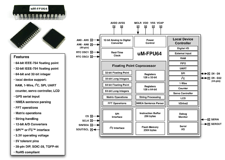
I have been poking around looking at floating point processors and have come across a very interesting chip that I have bookmarked for future investigation, the Micromega uM-FPU64. So far I have not been able to find anyone with stock on this chip other than the earlier V3.1 32 bit version. For USD25.00 in single unit quantities, this is quite the bargain.
Features
64-bit and 32-bit Floating Point
A comprehensive set of 64-bit and 32-bit floating point operations are provided.
See the uM-FPU64 datasheet for details.
64-bit and 32-bit Integer
A comprehensive set of 64-bit and 32-bit integer operations are provided.
See the uM-FPU64 datasheet for details.
User-defined Functions
User-defined functions can be stored in Flash memory. Flash functions are programmed through the SERIN/SEROUT pins using the uM-FPU64 IDE. A high level language is supported, including control statements and conditional execution.
Matrix Operations
A matrix can be defined as any set of sequential registers. The MOP instruction provides scalar operations, element-wise operations, matrix multiply, inverse, determinant, count, sum, average, min, max, copy and set operations.
FFT Instruction
Provides support for Fast Fourier Transforms. Used as a single instruction for data sets that fit in the available registers, or as a multi-pass instruction for working with larger data sets.
Serial Input / Output
When not required for debugging, the SERIN and SEROUT pins can be used for serial I/O. A second asynchronous serial port, with hardware flow control, is also available as a local device using the DEVIO instruction.
NMEA Sentence Parsing
The serial input can be set to scan for valid NMEA sentences with optional checksum. Multiple sentences can be buffered for further processing.
String Handling
String instructions are provided to insert and append substrings, search for fields and substrings, convert from floating point or long integer to a substring, or convert from a substring to floating point or long integer. For example, the string instructions could be used to parse a GPS NMEA sentence, or format multiple numbers in an output string.
Table Lookup Instructions
Instructions are provided to load 32-bit values from a table or find the index of a floating point or long integer table entry that matches a specified condition.
MAC Instructions
Instructions are provided to support multiply and accumulate and multiply and subtract operations.
A/D Conversion
Multiple 12-bit A/D channels are provided (six on 28-pin device, nine on 44-pin device). The A/D conversion can be triggered manually, through an external input, or from a built-in timer. The A/D values can be read as raw values or automatically scaled to a floating point value. Data rates of up to 10,000 samples per second are supported.
Real-Time Clock
A built-in real-time clock is provided, for scheduling events or creating date/time stamps.
Timers
Timers can be used to trigger the A/D conversion, or to track elapsed time. A microsecond and second timer are provided.
External Input
An external input can be used to trigger an A/D conversion, or to count external events.
Foreground/Background Processing
Event driven foreground/background processing can be used to provide independent monitoring of local peripherals. The microcontroller communicates with the foreground, while background processes can be used to monitor local device activity.
Local Device Support
Local peripheral device support includes: RAM, 1-Wire, I2C, SPI, UART, counter, servo controller, LCD, and VDrive2 devices. The uM-FPU64 can act as a complete subsystem controller for GPS, sensor networks, robotic subsystems, IMUs, and other applications. Local devices are assigned to digital I/O pins at run-time, and controlled with the DEVIO instruction.
Low Power Modes
When the uM-FPU64 chip is not busy it automatically enters a power saving mode. It can also be configured to enter a sleep mode which turns the device off while preserving register contents. In sleep mode the uM-FPU64 chip consumes negligible power.
Firmware Upgrades
When updates become available, the uM-FPU64 firmware can be upgraded in the field using the uM-FPU64 IDE software.