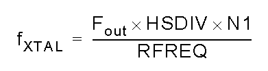
The relationship between the various frequency setting elements is described as follows:
As previously mentioned, the output frequency is the result of the DCO frequency divided by the product of two divisors. The DCO frequency is the product of a crystal frequency in the 114.25 MHz range and a settable reference frequency and must remain within the range of 4.85 to 5.67 Ghz. RFREQ has 38 bits of resolution allowing for a theoretical frequency setting resolution of 0.09 ppb at the test frequency of 114.285 MHz.
The HSDIV and N1 values have additional restrictions on them, specifically HSDIV can have the values 4, 5, 6, 7, 9 or 11. N1 can be 1 or any even number up to 128 inclusive (1, 2, 4, 6, ... 128).
Typically at startup you would determine the fxtal value specifically for your chip:
By interrogating the chip, one can determine the values for HSDIV, N1 and RFREQ. By knowing the default startup frequency, the crystal frequency can be calculated. In my case, HSDIV = 11, N1 = 8 and RFREQ is 0x2B6109f08. Dividing this value by 2^28 gives me 0x2b as the integer portion or 43 decimal. To figure out the fractional part one would divide 0x6109f08 (the least significant 28 bits of RFREQ) by 2^28. Working in decimal instead of hex:
0x6109f08 = 101752584 / 2^28 = 0.3790579140
Adding this to the integer portion gives me a RFREQ value of 43.3790579140. Plugging this and the other knowns into the formula above gives me:
fxtal = (56320000 * 11 * 8) / 43.3790579140 = 114252365.964832 or 114.252365 Mhz
The datasheet states that the crystal frequency is only accurate to +/- 2000 ppm at 114.285 Mhz, or about +/- 0.22857 so my device is within the pretty horrible specification.
So, running this the other way, the output frequency is found as:
fout = (114252365 * 43.3790579140) / 11 * 8 = 56319999.524391 = 56.32 Mhz
A guy could envision a mechanism wherein you output a WWV frequency and tweak RFREQ until zero beat and then store the value for future reference, but the known frequency technique will get you very close.
If the DCO frequency is only moved +/- 3500 ppm, the oscillator output will be phase continuous. This should make implementing protocols such as WSPR, JT65 and the like much cleaner than my previous work using the Parallax Propeller. Also, in theory there is .42 Hz frequency resolution capable which would allow for much closer FSK tone shifts used in WSPR than the 1Hz resolution I had with the propeller.
It is unclear from the datasheet what is precisely meant by the +/- 3500 ppm figure. One interpretation is that once you have moved a total of 3500 ppm from whatever frequency you last set using the "large frequency change technique", you would have to recalculate the RFREQ and divisor values and set them back to the device. In my experience, most of the Arduino implementations I have reviewed have taken a flavor of this approach. While this is certainly safe, it is unlikely to be necessary. The other interpretation I have of the datasheet is that you could move the DCO over its entire range without recalculating parameters and do it in a phase continuous manner as long as no single frequency change is more than 3500 ppm. My interpretation is that once you have changed the frequency by either of these mechanisms, the new DCO frequency (not the output frequency) becomes the new "center frequency" described in the datasheet. So, under my theory, you could move the output frequency a total of 5.67 - 4.85 GHz = 0.82 Ghz 3500 ppm at a time. Of course, this would require a different part than I have which only has a range of 10-160 Mhz. Under this theory, as long as you didn't jump more than 17.5 Mhz between frequency settings, you only have to recalculate RFREQ and the change in frequency could be done phase continuous. This theory I have not yet tested.
More to come...
Messing around with the Si570 chip that is used in the Minima transceiver designed by Farhan Akhtar. This is my lash-up:
After a bit of tweaking, I have the oscillator working. It is no picnic trying to interpret the Si570 datasheet however.
Interestingly enough most of the code implementations I have looked at for the Arduino make a couple of errors in interpretation of the datasheet. The Si570 is not really fun to program, but it has a number of benefits going for it.
My particular chip is a 10-160 MHz CMOS model. When I first power it up, it comes up at 56.320 MHz. The datasheet is not explicit on this, but supposedly the individual parts are "tuned" at the factory to their default frequency by adjusting the various parameters that are used to set the frequency. However, the datasheet does not provide very flattering stability numbers and nowhere does it provide a statement of how closely it is calibrated in the factory.
So, in the absence of highly accurate frequency measurement capabilities you are faced with having to calculate the internal crystal frequency based on the default output frequency (from the datasheet) after reading the frequency setting parameters from the chip itself.
The Si570 requires mathematical calculations with 38 bits of precision in order to accurately set it's frequency. Most Arduino implementations rely on double precision floating point math functionality. However, the Arduino implementation of double precision is in fact identical to its single precision floating point. Namely double = float data types silently behind the scenes. So, most of these implementations give up on the number of digits of precision required to control the Si570 even down to the 1 Hz level. Theoretically you should be able to set the frequency to within .42 Hz, but the unfortunate floating point double precision implementation on Arduino prevents even 1 Hz resolution.
The Si570 stores a reference frequency used in the output frequency calculation as a 38 bit values where 10 bits are use as a decimal multiplier. The remaining 28 bits are a fractional multiplier stored as an integer value scaled by 2^28.
The internal DCO is constrained to 4.85 to 5.67 GHz determined by the internal crystal frequency multiplied by a reference frequency. According to the settings in my chip, I calculate my crystal frequency to be 114.252365 MHz. Secondarily, frequency excursions of the DCO can be done in a phase continuous manner if the change in frequency is no more than +/- 3500 PPM. Many implementations however are calculating this based on the output frequency rather than the DCO frequency in error. Frequency excursions larger than this require the DCO to be stopped and restarted in a non-phase continuous manner that can take upwards of 10 ms to complete. Circuitry sensitive to runt pulses may require resetting after this operation.
The output frequency is the DCO frequency divided by the product of two divisors. There are additional restrictions on these two divisors.
More to follow...
Seems that 20 metres continues to be active with DX this evening. Currently listening to OD5ZZ from Tripoli, Lebanon. The band is much more quiet, but then again the weekend contest has no doubt ended. UT7UJ is active from Kiev, Ukraine towards the upper end of the band. It is sure nice to hear DX stations again on the bands after so much lack of propagation. ZS3CX is on from South Africa, T88XT from Palau, VK4LJ from Australia, and ZL2BQ from New Zealand are all quite loud.
Managed to get enough of the shack cleared out that I could do some listening on 20 metres last evening. I was pleasantly surprised how active the bands were, including well into the evening. The contest weekends raise the question in my mind just how dead the bands are as opposed to just how "inactive" the bands are. It seems that just about every contest weekend I can hear all sorts of DX but otherwise the bands have the appearance of being dead.
I listened to a number of Kuwait stations, New Zealand and mid-Atlantic stations working pile-ups. After listening to one particular pileup for about an hour, there was momentary lull and I tossed my call sign out to 9K2WA using QRP (5 watts) on SSB and he came right back to me and gave me the obligatory 59 signal report. (Yeah right...) But he was about 20 over S9, so who knows how strong I really was on his end.
Listening to AM broadcast band tonight and am hearing Canadian stations, quite strongly. 31 and 49 metre bands are quite active this evening as well. Crisp and clear evenings can be fun listening.
Been playing around with crystal radios lately. I have a loose coupled radio that consists of a pre-selector tuned circuit, a detector with a 1N34 germanium detector than can be switched out to allow external detectors to be used with the tuning circuits. Lastly, I have a wave trap tuned circuit that can be used to null out strong adjacent signals that might otherwise swamp the desired signal. These three modules are all built up in separate boxes and just placed near each other to couple together as strongly or weekly as desired by just varying the distance between them.
Now I am playing around with point contact semiconductors. This one is galena though I have some iron pyrite I would like to try as well.
I have built a few "fox-hole" receivers using the old blue double edge razor blades and a pencil but never got a chance to play around with point contact rectifiers made from minerals until now. Should be fun.
...when you combine a dog bumper launcher...
...with a 22 caliber blank cartridge loaded in the handle of this rather innocuous looking device?
Well... Tie a bit of kite string around the bumper (the white bit on the end), make some big loops on the ground with the line, insert ear plugs, stand behind and well clear of the line, pull back the spring loaded plunger on the bottom and it's bye-bye-bumper...
I used it today to launch over my house (which has a 45 degree (12/12 pitch) metal roof) a belaying line so I could get up there and clean some moss off the skylights and inspect the seals.
The bumper flew about 200' in the air before the trailing line slowed it down and dropped it in the front yard. You will get the neighbor's attention as the sound of a gun-shot rings through the neighborhood... I live on some acreage out of the city limits, so no boys in blue arrived on my doorstep. Guess I will fail the GSR test at the airport security checkpoint, eh?
I am not sure I can be very accurate with this thing to carefully place antenna lifting lines, but it certainly worked a treat for my get a line over the house to anchor to the pickup truck activity.
We of course had to turn a pack of golden retrievers loose to chase an untethered bumper which was a bit of a riot on a sunny Saturday in the northwest.
I have been getting the itch to try out a horizontal loop antenna for some time now. At the recent Salmoncon event, Eldon - WA0UWH put up a 40 metre vertical delta loop that we fed with 450 ohm ladder line. The results were, in a word, amazing. The top of the delta was at about 100' with the other two sides hanging downward and joined at the centre by the feed line. Running Eldon's FT817 at 5 watts, if we could hear it, we could work it.
Wanting to duplicate these kinds of results at home, I am keen to try out a loop, but in my location, I am only able to obtain about 50 feet of elevation. I am also interested in top band (160 metres) so a bigger loop is in order. This will require about 514 feet of wire which works out to about 128.5 feet on a side.
Looking at my site, I have four candidate trees for supports that will provide the ability to build a corner-fed trap trapezoid loop. The proposed site plot looks like this:
The building is oriented the long way north/south and with this orientation of the loop, I would feed it at the lower left (southwest) corner. Each of the legs is at least 180' long, so there would be plenty of room for a 160 metre loop. I wish I could get it up higher, but I guess that will have to wait for trees to grow.
Been a long time since I have been blogging at all. Happy to say it is because I have been very busy with the new job and getting settled into a new routine. I was out of work for 4 months after being laid off from Microsoft and am now back working with Dynon Avionics as a Senior Software Developer. I am having fun and working on some interesting projects that allow me to exercise both my hardware and software skills.
I have been playing around with PSoC devices from Cypress (www.cypress.com). Specifically I am playing with PSoC 1 devices. We are using them in a number of our products and in my new role, I found it necessary to learn about these devices and effectively take on another microcontroller. Pretty fun and I hope to incorporate some of these devices into some of my ham radio projects in the near future. Stay tuned...
It is a beautiful sunny warm summer day in Seattle. Been out this morning enjoying the sun and running errands. I have fired up the Raspberry Pi and thought I would try to update the blog from the Midori web browser included in the Wheezy build.
Spent way too many hours yesterday in the print shop getting an order out last evening and today Joan is off to eastern Washington to pick up a Fjord pony so I thought I would play a bit with the Raspberry Pi.
I ordered a couple 32 gig memory cards and will be trying to get a couple of different distributions working on them.
It is good to be working again after being laid off from Microsoft back in January. I am now working at Dynon Avionics in Woodinville doing software for their avionics product line. Happy to be employed again!
We have had one of those fantastic weeks of sunshine here in the northwest that make it one of the best places to live. When the sun is out in Seattle, there is nothing better. Unfortunately, there are a whole lot of grey sky days in between.
I am currently scheduled to go pick up my airplane Tuesday after it's rather lengthy annual inspection. However, it is looking like the weather may not hold until then. We shall see.