The Arduino Due Timers or Counter Timer (TC) as they are called are a bit different implementation from the 8 bit Arduino devices. There is a lot of functionality in the Due Timer Counter module and it is not a simple thing to describe it fully so I will likely break this into several postings.
The SAM3X8E CPU has 3 Timer Counters (TCs) named TC0, TC1, TC2. Each TC includes three identical 32-bit channels. Each channel can be independently programmed to perform a wide range of functions including frequency measurement, event counting, interval measurement, pulse generation, delay timing and pulse width modulation (PWM).
Each channel has three external clock inputs, five internal clock inputs and two multi-purpose input/output signals which can be configured by the user. Each channel drives an internal interrupt signal which can be programmed to generate processor interrupts.
The TC embeds quadrature decoder logic connected in front of the 3 timers and driven by TIOA0, TIOB0 and TIOA1 inputs. When enabled, the quadrature decoder performs input line filtering and decoding of quadrature signals. We will not be covering this feature in these postings.
The TC block has two global registers which act upon all three TC channels. The Block Control Register allows the three channels to be started simultaneously with the same instruction. The Block Mode Register defines the external clock inputs for each channel, allowing them to be chained.
Clocks are assigned to Timer Counters as follows:
- TIMER_CLOCK1 - MCK/2
- TIMER_CLOCK2 - MCK/8
- TIMER_CLOCK3 - MCK/32
- TIMER_CLOCK4 - MCK/128
- TIMER_CLOCK5 - SLCK
MCK is the master clock (84 MHz) and SLCK is the slow clock (32 kHz). It should be noted that it is possible to select the slow clock as the master clock, which case TIMER_CLOCK5 input is equivalent to the master clock. As will be seen later, TCs can be chained together using the TIOA0, TIOA1, TIOA2 as an external clock input for subsequent TCs allowing further division of the clock frequency. I may get into clock chaining in further detail in a separate post.
This rather daunting image is the Timer Counter block diagramme. It is not as bad as it looks.

Channel signals seen above are as follows:
- XC0, XC1, XC2 - External Clock Inputs
- TIOA - Capture Mode: TC Input, Waveform Mode: TC Output
- TIOB - Capture Mode: TC Input, Waveform Mode: TC I/O
- INT - Interrupt Signal Output
- SYNC - Synchronization Input Signal
Each channel is organized around a separate 32-bit counter. The value of the counter is incremented at each positive edge of the selected clock. When the counter has reached the value 0xFFFFFFFF and wraps around to 0x00000000, an overflow occurs and the COVFS bit in TC_SR (Status Register) is set. The current value of the counter is accessible anytime by reading the Counter Value Register, TC_CV. The counter can also be reset by a trigger. In this case, the counter value resets to 0x00000000 on the next valid edge of the selected clock following the trigger event.
At the block level, input clock signals of each channel can either be connected to the external inputs TCLK0, TCLK1 or TCLK2, or be connected to the internal I/O signals TIOA0, TIOA1 or TIOA2 for chaining by programming the TC_BMR (Block Mode) register.
Each channel can independently select an internal or external clock source for its counter via the TCCLKS bits in the TC Channel Mode register (TC_CMR).
- Internal clock signals: TIMER_CLOCK1, TIMER_CLOCK2, TIMER_CLOCK3, TIMER_CLOCK4, TIMER_CLOCK5
- External clock signals: XC0, XC1 or XC2
The selected clock can be inverted using the CLKI bit in TC_CMR. This allows counting on the opposite edges of the clock. There is a burst function which allows the clock to be validated when an external signal is high. The BURST parameter in the Mode Register defines this signal (none, XC0, XC1, XC2).
Note that in all cases, if an external clock is used, the duration of each of its levels must be longer than the master clock period and the external clock frequency must be at least 2.5 times lower than the master clock.
Here is a block diagramme of the clock selection logic:

We still have not covered clock control, operating modes, or triggers, but we will touch on these topics as we work through examples.
Ok, enough background about Due timers for now and on to the first practical example. In this example we will define a function that allows the configuration of a TC to generate a square wave at a relatively low frequency of the caller's choice.
Firstly, let's think about clocking our timer. We have a system clock speed of 84 Mhz that can be divided by 4 different divisors (2, 8, 32 and 128) and the slow clock. So, the available timer clock speeds are:
- 42 MHz
- 10.5 MHz
- 2.652 MHz
- 656.25 kHz
- 32 kHz
To start up a timer, we need to deal with at least 4 different bits of information when doing simple operations with TCs.
- The Timer Counter (TC) you wish to use
- The channel in that TC you with to use
- The IRQ if interrupts are used
- The frequency of the timer
So, we will create a function to encapsulate all this to get a simple timer running. The timer will generate a square wave at the specified frequency.
There is a bit of housekeeping that needs to occur.
- We need to enable the ability to modify the power management controller's registers.
- We need to enable a specific peripheral clock specified by the IRQ.
- We need to set the TC configuration.
Power Management Controller calls look like this. We need to turn off write protection and then enable the peripheral clock for TC1 Channel 0.
pmc_set_writeprotect(false);
pmc_enable_periph_clk(ID_TC3);
You could also use TC3_IRQn rather than ID_TC3 as they are both different names for the same constant value. It is more clear to use the correct constant name, but as we will see shortly, it does simplify the implementation if we don't.
TC_Configure is used to configure a TC to operate in a given mode. The timer is stopped after configuration and must be restarted with TC_Start(). All interrupts of the timer are also disabled.
We will select Waveform Mode and instruct the TC to count up with a reset on register C (RC) compare. The following graphic depicts this mode, though it seems to imply the maximum counter value is 0xffff which is not true. With 32 bits, the maximum counter value would be 0xffffffff.

TC configuration is accomplished with the following code. We will use Timer Clock 4 (master clock / 128 = 656.25 kHz) as for this example we will be generating low frequency waveforms. The function takes the TC and Channel as the first two parameters. The last parameter sets bits to indicate the fact we are in Waveform mode, only counting up to the maximum value specified in Register C (RC) and which of the 5 clocks we will use.
TC_Configure(tc, channel, TC_CMR_WAVE | TC_CMR_WAVSEL_UP_RC |
TC_CMR_TCCLKS_TIMER_CLOCK4);
Now we need to set Register A (RA) to be the clock count where our output (TIOA) goes high and Register C (RC) at the clock count where our output goes low. See the graphic above. We chose points that would generate a symmetrical 50% duty cycle square wave. Register C is set to the maximum count specified by the clock frequency divided by the desired frequency.
uint32_t rc = VARIANT_MCK / 128 / freq;
TC_SetRA(tc, channel, rc / 2); // 50% duty cycle
TC_SetRC(tc, channel, rc);
Now we enable the Register C (RC) compare interrupt. This bit is a little strange, because we have both an interrupt enable register and an interrupt disable register. I suspect this is so that a complete set of interrupts that you might need can be set in the interrupt enable list and sub-sets turned off by modifying the list of disabled interrupts. This way you don't have to remember which ones were enabled previously. This code enables only the RC compare interrupt and disables everything except RC compare interrupt, or so I believe.
tc->TC_CHANNEL[channel].TC_IER = TC_IER_CPCS;
tc->TC_CHANNEL[channel].TC_IDR = ~TC_IER_CPCS;
Start the timer running again.
TC_Start(tc, channel);
And tell the Nested Interrupt Controller to enable our IRQ.
NVIC_EnableIRQ(irq);
Simple, eh? Yeah... Nothing to it... Here is the entire function:
void TimerStart(Tc *tc, uint32_t channel, IRQn_Type irq, uint32_t freq)
{
pmc_set_writeprotect(false);
pmc_enable_periph_clk((uint32_t) irq);
TC_Configure(tc, channel, TC_CMR_WAVE | TC_CMR_WAVSEL_UP_RC |
TC_CMR_TCCLKS_TIMER_CLOCK4);
uint32_t rc = VARIANT_MCK / 128 / freq;
TC_SetRA(tc, channel, rc/2); // 50% duty cycle square wave
TC_SetRC(tc, channel, rc);
TC_Start(tc, channel);
tc->TC_CHANNEL[channel].TC_IER=TC_IER_CPCS;
tc->TC_CHANNEL[channel].TC_IDR=~TC_IER_CPCS;
NVIC_EnableIRQ(irq);
}
Whew... Still with me? Ok!
Now we will implement an ISR handler that just toggles the LED on digital pin 13 on and off every time the timer fires an interrupt. It also has to read the status of the Timer Counter (TC) in order to allow the next interrupt.
volatile boolean ledOn;
void TC3_Handler()
{
TC_GetStatus(TC1, 0);
digitalWrite(13, ledOn = !ledOn);
}
Ok, so given that we are only interrupting when Register C compare match occurs (see graphic above), and we are toggling pin 13 on every interrupt, we effectively divide the frequency that the led blinks at by two. If we want the frequency of the led blinking to match the frequency of the timer, we will need to interrupt on Register A compare match as well. The code changes to implement this would be to just enable the interrupt on RA compare as well as RC compare.
tc->TC_CHANNEL[channel].TC_IER= TC_IER_CPCS | TC_IER_CPAS;
tc->TC_CHANNEL[channel].TC_IDR=~(TC_IER_CPCS | TC_IER_CPAS);
So, the only thing remaining is to implement the setup function and stand back... We set the LED pin to output and initialize timer TC1, channel 0 using the IRQ TC3_IRQn (from the table above) with a frequency of 1 Hz.
void setup()
{
pinMode(13, OUTPUT);
TimerStart(TC1, 0, TC3_IRQn, 1);
}
So all of this is to blink a freaking LED at a 1 Hz rate. Amazing flexibility (and the associated complexity) comes at the bit of a steep learning curve. Here is the complete listing for your reference.
volatile boolean ledOn;
//TC1 ch 0
void TC3_Handler()
{
TC_GetStatus(TC1, 0);
digitalWrite(13, ledOn = !ledOn);
}
void TimerStart(Tc *tc, uint32_t channel, IRQn_Type irq, uint32_t freq)
{
pmc_set_writeprotect(false);
pmc_enable_periph_clk(irq);
TC_Configure(tc, channel, TC_CMR_WAVE | TC_CMR_WAVSEL_UP_RC |
TC_CMR_TCCLKS_TIMER_CLOCK4);
uint32_t rc = VARIANT_MCK / 128 / freq;
TC_SetRA(tc, channel, rc >> 1); // 50% duty cycle square wave
TC_SetRC(tc, channel, rc);
TC_Start(tc, channel);
tc->TC_CHANNEL[channel].TC_IER= TC_IER_CPCS | TC_IER_CPAS;
tc->TC_CHANNEL[channel].TC_IDR=~(TC_IER_CPCS | TC_IER_CPAS);
NVIC_EnableIRQ(irq);
}
void setup()
{
pinMode(13, OUTPUT);
TimerStart(TC1, 0, TC3_IRQn, 1);
}
void loop()
{
}
More to come, but have fun with this if you are so inclined. I am always willing to help out if you have questions. Drop me a note at ko7m at arrl dot net or comment here and I will do my best.
Do you know how to use the TIOA waveform directly without any interrupts or anyway to get the timer compare to operate at a waveform over 1 MHz.
ReplyDeleteHello Andross,
DeleteIf you wish to use the TIOAx output directly instead of handling in interrupt, you would need to tell the PIO controller of the uC to connect the hardware pins to the corresponding peripheral. If you want to route the TIOAx pin to the outside, you would need to set up the PIO something like this:
int ulPin = 2; // Timer0 in this case
PIO_Configure(g_APinDescription[ulPin].pPort,
g_APinDescription[ulPin].ulPinType,
g_APinDescription[ulPin].ulPin,
g_APinDescription[ulPin].ulPinConfiguration);
I found this code fragment in wiring_analog.c in the Arduino 1.5.x branch.
https://github.com/arduino/Arduino/blob/ide-1.5.x/hardware/arduino/sam/cores/arduino/wiring_analog.c#L329
What do you think about the usefulness/capability of this library?
ReplyDeletehttps://github.com/ivanseidel/DueTimer
Hello Osqui. I took a quick look at your library. I think it is quite useful as is, but I would probably do things a little differently. For one thing, I would certainly not instantiate 9 timers automatically as a result of using this library.
DeleteThe examples I think could also be improved to include more than basic timer interrupt on a periodic basis kinds of examples. Perhaps other examples would be useful, such as measurment of frequency or period, arbitrary waveform generation or quadrature decoding.
That said, I think it is a very good effort and useful in its own right. Nice work.
Thanks a lot for your time and your advices!!
DeleteHi, I am trying to find the source code of these functions you are using in this tutorial, like TC_GetStatus(TC1, 0) for example. Where are they located? I'm trying to find out if there is a method that can let me know when the timer signal switches from low to high and high to low,how would I do that?
ReplyDeleteTo the best of my knowledge, the source code has not been provided for much of the SAM code base including the TC_GetStatus component you ask about. Looking at a map file of a project that calls this function, I see the following:
Delete.text.TC_GetStatus
0x0008077c 0x8 C:\Users\Jeff\AppData\Roaming\Arduino15\packages\arduino\hardware\sam\1.6.3\variants\arduino_due_x/libsam_sam3x8e_gcc_rel.a(tc.o)
0x0008077c TC_GetStatus
So, it looks like this is supplied as a library rather than in source format.
This comment has been removed by a blog administrator.
ReplyDeleteHi Jeff, I am very interested to see you are into the DUE timers. Here is my use case, I would be interested to hear your opinion on what I am trying to do. The DueTimer library does not include the functionality I need, so I am planning on extending it... I am still a newbie on the Arduino stuff ...
ReplyDeleteI have a u-blox GPS receiver and I want to know the time as accurately as possible on the arrival of a cosmic ray trigger pulse.
I want to run a timer using the MCLK/2 (84 MHz / 2) internal clock, and to reset this counter to zero each second via an external input coming from the PPS (Pulse Per Second) of the u-blox. The external trigger from the analogue electronics board can be configured to latch the SAM3X counters 32bit value into REGA to be read later in the arduino interrupt handler.
This means that no interrogation over the u-blox serial line is needed to know within 2 ticks of the counter clock when the event occurred <100ns. It also means the Raspberry PI can take its time to read the latched counter value.
So with this scheme I would be able to time stamp my events by counting in MCLK/2 clock from the GPS PPS.
What do you think ?
Here is some working code for time stamping events, in my case cosmic rays.
DeleteThe D2 pin is connected to my GPS PPS timing signal (PS I strongly recommend using a pull down resistor to eliminate noise).
The D5 pin is connected to toe OR of the PPS and the event you want to time stamp. (Use a diode to isolate D2 PPS from D5 PPS). It turns out that when TC0 and TC2 both get the PPS at the same time, then TC0 always gets it first !
You can get my implementation here ...
https://www.dropbox.com/s/3swor6wx3088qqo/event_tag.ino?dl=0
Enjoy
Hi Julian! Sorry to be slow in responding as I have been dealing with my wife's broken and dislocated arm from a fall on New Years Day. Bummers... Anyway, I like your idea about how to time stamp events. Very clever idea. I apppreciate you sharing your implementation and will be sure and check it out. Congratulations on getting it working. Are you able to share why you want to timestamp cosmic rays?
DeleteHi Julian, I was looking for your code example, I want to be able to detect the time of arrival of a data packet accurately referenced to GPS time. Is you code still available?
DeleteHi Jeff,
ReplyDeleteSince retiring from engineer at CERN, I have just joined a collaboration with a bunch of CERN guys building a cosmic ray telescope.
When a cosmic ray hits the earths atmosphere it creates a conical shower of secondary particles that rain down over what would be an elliptic
area on the ground if the surface was flat. Thus if we were to cover the ground with small cosmic ray detectors that had good GPS chips (U-blox NEO-M8)
then each detector would know its location (longitude, latitude, elevation).
By using the trick I coded for the DUE counters, each detector could time stamp the arrival time of any particle that hit it. This information is passed
over the DUE serial link to a raspberry PI-2 that transmits this information, probably over UDP, to a central server that can determine the direction
from which the cosmic ray came by interpreting the time-stamps; and its energy which is proportional the area of the event on the ground and the elevation of the
detector. (If the shower foot print was a circle -> equal time stamps -> then it came straight down over its center - if you get me)
So the idea is to design a single cosmic ray detector for a low price <500$ and then when the design is finalized to persuade as many people as
possible to build and run one, geeks, school scientists, and other weirdos that like doing that sort of thing. The more we get out there the better the
data we get. So its just a fun project with some really interesting and useful science behind it.
Cheers Julian
Here is the final version of the Timer sketch, it turns out that the DUE disables interrupts in Serial.print and uses spin locks completely disabling interrupts while printing. In the link below I add some logic to bypass this problem.
ReplyDeletehttps://www.dropbox.com/sh/v0l92mtrjfu3cyn/AACRxkW5OMw8RNMfdHAn1FZRa?dl=0
I may have given the wrong link ---
ReplyDeletehttps://www.dropbox.com/sh/3i84soej3v4pwjs/AAAE8kqFCriz-QofUaPczMhLa?dl=0
Dear Jeff, your post usefull for me. I need to create program similar quadrature decoder but using pulse and direction.-
ReplyDeleteI have written a code with external interrupt but not count more than 125khz and i need count up/down more faster until 200Khz
what can i do?
73´Dx LW7EOF
Sergio Wandscheer
If you need to count faster with no other changes to the code, then you would pick an appropriate clock rate and set your RA and RC interrupt counts appropriately to generate the frequency output you would like as a 50% duty cycle. For example, if you use TIMER_CLOCK1 (42 MHz) then divide by the frequency you want (200kHz) as your RC value and 1/2 that as your RA value (for 50% duty cycle) that will give you the frequency you desire.
Deleteuint32_t rc = VARIANT_MCK / 2 / 200000;
TC_SetRA(tc, channel, rc / 2); // 50% duty cycle
TC_SetRC(tc, channel, rc);
I hope this helps!
Jeff
Hi jeff, thank you for your information, I am using your implementation of timer TC1, channel 0 using the TC3_IRQn with a frequency of 1 Hz, and I want to know how to Stop the Timer and later Restart it again?
ReplyDeleteRicardo
Hello Ricardo. To stop the timer:
DeleteTC_Stop(tc, channel);
And, to restart it:
TC_Start(tc, channel);
Hope this helps!
This comment has been removed by a blog administrator.
ReplyDeleteThis comment has been removed by a blog administrator.
ReplyDeleteHi Jeff,
ReplyDeleteThanks for this great post. I'm hoping you can help with a little problem I'm having. I have been able to blink an LED using the timer code you reference above but I wanted to expand the code a little. I modified the code to sweep a PWM signal to the LED to change its intensity every second. This worked great so I then decided to try to measure the output of a phototransitor at each PWM setting (between the 1 second intensity shifts). I placed this measurement code in the main loop and setup a Serial.println command to send the measured voltage value out to the console. This is where the code seems to fail. The code compiles and runs up until the first interrupt is called. The serial output stops and never restarts and the LED intensity does not change (its OFF to start). It seems like the Serial command in the main loop is breaking the interrupt cycle or getting stuck in an infinite loop somehow. Any insights would be appreciated.
Thanks.
Hi Brian,
DeleteI apologize, but I deleted the two redundant copies of your comment. The text was the same, so I reduced the number of them to one.
I wonder if I might have the benefit of commenting on the actual code you are having trouble with?
I cannot tell with certainty without seeing the code, but my suspicion is that you may be attempting to do Serial.println calls inside an interrupt handler. If so, you will find that Serial.println depends on interrupts to complete its task. Since interrupts are disabled while inside an interrupt handler, you now have prevented Serial.println to complete as interrupts are disabled. This is my best guess in the absence of seeing the code.
If you would not mind sharing the code, I can perhaps comment more specifically.
Thank you for your interest in my experiments with the Due.
The serial interface on the Arduino due actually switches interrupts off and dumps the text all in one go. Add a result it screws the timing up completely. To fix this problem i suggest you copy the text to a buffer instead (sprintf) and in the loop simply output one character. This way you only print when the timer logic is idle.I do this and the real time behavior is improved a lot. What's great about sonic this is that you can even print from within an isr.
ReplyDeleteWhile I believe that printing from within an ISR to serial output is completely possible within some set of constraints, one must keep in mind that at for example 9600 baud (a typically slow serial output and the default on a lot of systems) a single character output is still on the order of 0.96 ms which is an eternity in the grand scheme of things. One must keep in mind therefore that all processing time from within an ISR is time that cannot be spent elsewhere due to interrupts being disabled. In one of my work projects, I have timer interrupts for a servo control loop firing every 250 us. The computational requirements during each timer interrupt were on the order of 170-180 us. This means that 70% of the available MIPS are being spent on this one activity. Clearly it had to change and is now in the 50 us range on each interrupt leaving much more acceptable levels of processor available for other tasks. The message is simple. Keep your ISR routines short, sweet and to the point.
DeleteOK. Here we go again. ;) please excuse me if there are multiple posts.
ReplyDeleteI'm happy to share the code. It is nothing special or fancy. In fact this is copied from another tutorial I found on the web before I found yours. I believe the code is very similar to what you have above.
Thanks for offering to review it.
Best Regards,
Brian
Code starts below this line
int led = 9; // the PWM pin the LED is attached to
int brightness = 0; // how bright the LED is
int fadeAmount = 5; // how many points to fade the LED by
// Black magic
void startTimer(Tc *tc, uint32_t channel, IRQn_Type irq, uint32_t frequency) {
pmc_set_writeprotect(false);
pmc_enable_periph_clk((uint32_t)irq);
TC_Configure(tc, channel, TC_CMR_WAVE | TC_CMR_WAVSEL_UP_RC | TC_CMR_TCCLKS_TIMER_CLOCK4);
uint32_t rc = VARIANT_MCK / 128 / frequency; //128 because we selected TIMER_CLOCK4 above
TC_SetRA(tc, channel, rc / 2); //50% high, 50% low
TC_SetRC(tc, channel, rc);
TC_Start(tc, channel);
tc->TC_CHANNEL[channel].TC_IER = TC_IER_CPCS;
tc->TC_CHANNEL[channel].TC_IDR = ~TC_IER_CPCS;
NVIC_EnableIRQ(irq);
}
// the setup routine runs once when you press reset:
void setup() {
// initialize serial communication at 9600 bits per second:
Serial.begin(9600);
// declare pin 9 to be an output:
pinMode(led, OUTPUT);
// Start timer. Parameters are:
// TC1 : timer counter. Can be TC0, TC1 or TC2
// 0 : channel. Can be 0, 1 or 2
// TC3_IRQn: irq number. See table.
// 40 : frequency (in Hz)
// The interrupt service routine is TC3_Handler. See table.
startTimer(TC1, 0, TC3_IRQn, 2);
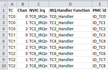
// Paramters table:
// TC0, 0, TC0_IRQn => TC0_Handler()
// TC0, 1, TC1_IRQn => TC1_Handler()
// TC0, 2, TC2_IRQn => TC2_Handler()
// TC1, 0, TC3_IRQn => TC3_Handler()
// TC1, 1, TC4_IRQn => TC4_Handler()
// TC1, 2, TC5_IRQn => TC5_Handler()
// TC2, 0, TC6_IRQn => TC6_Handler()
// TC2, 1, TC7_IRQn => TC7_Handler()
// TC2, 2, TC8_IRQn => TC8_Handler()
}
// the loop routine runs over and over again forever:
void loop() {
// read the input on analog pin 0:
int sensorValue = analogRead(A0);
// Convert the analog reading (which goes from 0 - 1023) to a voltage (0 - 3.3V):
float voltage = sensorValue * (3.3 / 1023.0);
// print out the value you read:
Serial.println(voltage);
// wait for 30 milliseconds to see the dimming effect
//delay(500);
}
void TC3_Handler()
{
// You must do TC_GetStatus to "accept" interrupt
// As parameters use the first two parameters used in startTimer (TC1, 0 in this case)
TC_GetStatus(TC1, 0);
// set the brightness of pin 9:
//digitalWrite(led, brightness);
analogWrite(led, brightness);
Serial.println(brightness);
// change the brightness for next time through the loop:
brightness = brightness + fadeAmount;
// reverse the direction of the fading at the ends of the fade:
if (brightness == 0 || brightness == 50) {
fadeAmount = -fadeAmount ;
}
}
You missed the point, you store text in a buffer in the isr which gets probed our char by char on the loop.
ReplyDeletecode
ReplyDelete// These two routines are needed because the Serial.print method prints without using interrupts.
// Calls to Serial.print block interrupts and use a wait in kernel space causing all ISRs to
// be blocked and hence we could miss some timer interrupts.
// To avoid this problem call PushTxt to have stuff delivered to the serial line, PushTxt simply
// stores your text for future print out by PutChar. The PutChar routine removes one character
// from the stored text each time its called. By placing a call to PutChar in the outermost loop
// of the Arduino loop function, then for each loop one character is printed, avoiding blocking
// of interrupts and vastly improving the loops real time behaviour.
// Copy text to the buffer for future printing
void PushTxt(char *txt) {
int i, l = strlen(txt);
// If this happens there is a programming bug
if (l > TBLEN) { // Can't handle more than TBLEN at a time
terr = TXT_TOOBIG; // say error and abort
return;
}
// If the buffer is filling up to fast throw it away and return an error
if ((l + tsze) >= TBLEN) { // If there is no room in the buffer
terr = TXT_OVERFL; // Buffer overflow
return; // Simply stop printing when txt comming too fast
}
// Copy the new text onto the ring buffer for later output
// from the loop idle function
for (i=0; i<l; i++) {
txtb[txtw] = txt[i]; // Put char in the buffer and
txtw = (txtw + 1) % TBLEN; // get the next write pointer modulo TBLEN
}
tsze = (tsze + l) % TBLEN; // new buffer size
}
// Take the next character from the ring buffer and print it, called from the main loop
void PutChar() {
char c[2]; // One character zero terminated string
if (tsze) { // If the buffer is not empty
c[0] = txtb[txtr]; // Get the next character from the read pointer
c[1] = '\0'; // Build a zero terminated string
txtr = (txtr + 1) % TBLEN; // Get the next read pointer modulo TBLEN
tsze = (tsze - 1) % TBLEN; // Reduce the buffer size
Serial.print(c); // and print the character
}
}
// Arduino main loop does all the user space work
void loop() {
PutChar(); // Print one character per loop !!!
}
end code
Sorry I am not sure how to publish code on this page ...
ReplyDeleteSo the idea is you just push text from anywhere it takes hardly any time to copy to a buffer.
In loop any text in the buffer is output one character at a time. If the buffer overflows the text gets thrown away.
So this allows printing to the serial brain dead arduino port without screwing up the real time performance. We use this method in out cosmic-pi project and it works fine.
http://facebook.com/cosmicpi
About keeping the ISR short and sweet, I totally agree. This technique is however useful to debug code.
ReplyDeleteSorry ... here is how you call it ...
ReplyDeletesprintf(txt,"{'location':{'latitude':%f,'longitude':%f,'altitude':%f}}\n",latitude,longitude,altitude);
PushTxt(txt);
Very good Julian. I believe I understand what you are saying. The technique of building a circular buffer in the ISR and emptying it in the main loop is very appropriate. I further understand the issue of printing a bunch of text might prevent other interrupts from happening during portions of that serial output. It is certainly a balancing act of ensuring that there is enough CPU processing power available to handle all processing, be it computational or I/O processing. It also points to the need to develop techniques such as you have done to allow spreading the available CPU time around. Besides optimizing code, other techniques might include careful interrupt priority tuning. Thank you for sharing your well thought out and implemented solution to a tricky problem. Well done sir.
Deletewhat is event counter? how it will be used in arduino due
ReplyDeleteIf you took the counter's clock input and connected it to an external pin that toggles when some event occurs, you are now clocking the counter based on those events happening. The value of the counter is the count of the events that occurred.
DeleteHi Jeff,
ReplyDeleteThank you for writing this post, it was the best resource I have found that actually addresses how to implement timer counters on the Arduino Due. I feel that now I am tantalisingly close to realising the controllable PWM generators that I want. I seem to have an issue when calling the TimerStart function however. The code I have currently can be found here: https://github.com/MattJH10/Arduino-Due-PWM/blob/master/DueTimerTest.ino
The loop function has been tested separately and does work but when the TimerStart function call is commented back in the serial stops working and the code doesn't seem to do anything. Can I define channel A and B at the same time? Have I got the right syntax for the timers? I would greatly appreciate your help.
Thank you.
One issue I see with the code you posted to github is that you are calling TimerStart in the setup() function but the pwmDuty[] values have not yet been set to any value so the values are non-deterministic. This will certainly cause random results. One possibly solution would be for you to initialize the pwmDuty[] values before calling TimerStart with reasonable defaults and then allow changing them in your main loop as you have implemented. Good luck!
ReplyDeleteHi Jeff.
ReplyDeleteI would like to ask for something about Arduino DUE timer, but can not find out the way to do it.
Is there any help to do it in the rigth way?
ind regards Kurt.
OZ8HZ
Hello Kurt,
DeleteJust post your reply here and I will respond. I do not allow immediately publishing replies or comments until I have reviewed them so your question or comment will not be immediately visible on my blog until after I have reviewed it. I am happy to field any question you might have.
Hi, Jeff.
ReplyDeleteI am trying to make a TACAN simulator (ground station) with the Arduino DUE.
I include , and use Timer1 to make squitter pulses. Timer2 is used to make Northburst an AUX.
To start Timer1: Timer1.attachInterrupt(T1IRQ).start(185);
When Timer1 gives irq, I has to start it again with a new period with the command: Timer1.start(JitterArray[jitterptr]);
JitterArray[jitterptr] is an array with random time 185uS +-20uS.
But the start-command is to slow, use ca. 100uS to start the timer.
Is there an quick methode to change the Timer1 period?
The DAC-routine in DUE is also to slow, so I make a R2R-ladder network on PORTD and store the pulsevalue with the command: PIOD->PIO_ODSR = puls360[DAC][ii]; in abouth 50nS.
Can this method be used to change the timer?
Kind regards Kurt
OZ8HX
Hello Kurt,
DeleteI am researching the timer start performance and will comment later. The DAC conversion is clocked off of the MKLC (84 MHz) divided by two (42 MHz). The conversion is complete after 25 clocks so best case is 0.595 us (595 ns). There is a small fifo on front of the DAC and when it is full the TXRDY bit will de-assert in the DAC control register indicating it is currently not ready for data. So if you need the 50 ns conversion speed, your R2R ladder is a simple solution.
Hello Kurt,
DeleteAt this moment in time I do not have time to research the best performance you can expect out of timer starts. You have not told me the performance that you require. One possible solution might be to eliminate the need to change the timer frequency at all and instead have it interrupt at the shortest period that you require and merely keep a counter that increments on every interrupt. You can then measure time changes in that increment and with a simple subtraction determine that your time period has expired. For example just pass the incrementing value into a function that needs to measure time. That function then can keep a static start timer count value and subtract it from the new value passed in to determine if sufficient time has passed. A simple subtraction will certainly perform better than the reconfiguration of a timer peripheral. Let me know how you get on with this project!
I has found a solution for Timer0 on the web.
ReplyDeletefor the moment I use this:
PIOA->PIO_SODR=1<<10; // pin19 high. Use 22ns. My marker.
REG_TC0_WPMR=0x54494D00; // enable write to registers
REG_TC0_CMR0=0b00000000000010011100010000000000; // set channel mode register (see datasheet)
REG_TC0_RC0=(jitter[jitterptr]); // counter period
REG_TC0_CCR0=0b101; // start counter
REG_TC0_IER0=0b00010000; // enable interrupt on counter=rc
REG_TC0_IDR0=0b11101111; // disable other interrupts
NVIC_EnableIRQ(TC0_IRQn); // enable TC0 interrupts
PIOA->PIO_CODR=1<<10; // pin19 low. My marker
It work, and use ~700 nS, but I has to find out how it work and how to set up on other timers.
Kurt
Hello Kurt,
DeleteI am delighted that you were able to find a solution that meets your performance requirements. I dare say that not all of that is going to be necessary in order to just change the period. You will certainly need it all on the initial setup, but if you are merely changing the counter period, resetting REG_TC0_RC0 to the new period and re-enabling the counter interrupt is likely all that would be necessary. Best of luck in your efforts!
Hi Jeff,
ReplyDeleteFrom a humble undergraduate, I'd like to thank you for contributing your decades of knowledge in a format that a novice can understand.
Please confirm my understanding on the following... Since you're utilising both RA and RC to construct a square wave, and you're using both the RA Compare Interrupt and the RC Compare Interrupt, would this program generate interrupts at twice the frequency of the square wave?
Kind Regards
Ivan (not Jimmy. That name was an artifact from my youth and I can't find the option to change it anymore...)
Hello Ivan,
ReplyDeleteI am honored that you find my writings useful. In this particular example, since I was toggling my GPIO pin on every RC interrupt the effect of that was the LED would blink at 1/2 the desired rate. So the simple solution was to interrupt at the start and end of the waveform. Other solutions exist such as setting RC to be 1/2 its calculated value and interrupting twice as fast while still just toggling the LED in the handler.
Kind regards,
Jeff
Good morning sir,
ReplyDeleteThanks you very much for your instruction, but you said that this function is apply for the low frequency application, if I want to sampling signal with frequency = 100kHz, can I use this code or what I have to do ?
If you need to count faster with no other changes to the code, then you would pick an appropriate clock rate and set your RA and RC interrupt counts appropriately to generate the frequency output you would like as a 50% duty cycle. For example, if you use TIMER_CLOCK1 (42 MHz) then divide by the frequency you want (100kHz) as your RC value and 1/2 that as your RA value (for 50% duty cycle) that will give you the frequency you desire.
Deleteuint32_t rc = VARIANT_MCK / 2 / 100000;
TC_SetRA(tc, channel, rc / 2); // 50% duty cycle
TC_SetRC(tc, channel, rc);
I hope this helps!
Jeff
Thank for your reply, I can sampling with the specific frequency, but I sampling two signal with two different sampling frequency, more over, I use some command: analogRead, analogWrite and digitalWrite in the interrupt function, so my problem is I can increase the frequency ( for example : signal1: 20kHz, signal2: 10kHz is maximum). I have read the clock speed of ADC, in datasheet it is 1MHz, but some people said the function analogRead() in a tight loop takes 39uS per loop, so I use:
ReplyDeleteadc_init(ADC, SystemCoreClock, ADC_FREQ_MAX,ADC_STARTUP_FAST); to reduce the time of this function, but nothing change. I don't know, where the problem is? Thank for any help.
I would remove the analogRead from the interrupt routine. In my experience on the Due, they will take about 3 microseconds to complete. I have not done timing of analogWrite. Nevertheless, if possible I would only perform critical operations during the interrupt and set flags that trigger the longer operations in main loop processing. If your only solution is to speed up the analogue conversion speed, try:
DeleteREG_ADC_MR = (REG_ADC_MR & 0xFFF0FFFF) | 0x00020000;
This should give you 3-4 microsecond analogReads at the cost of some noise in the conversion. If you need faster, I am afraid the Due is not going to be able to help you and you should look at restructuring your code to move the analogue conversions out of the interrupt handlers.
Thanks for your explanation sir. My desired frequency is 1kHz(not i Hz). Then what change should i provide in this code?
ReplyDeleteHi Jeff! Brilliant explanation of the timers. Is there an example anywhere of external interval measurement (i.e. time between pulses)
ReplyDeleteI don't have a working sample for you, but the concept is simple enough...
DeleteYou could use a GPIO input that is set up to interrupt on a pin change. This way anytime the pin changes state your ISR handler will get a chance to run. In this ISR handler you would start and stop a free-running timer. The timer value when you stop it is the amount of time that has passed. Depending on the span of time you need to measure and the resolution you need, you may well need external 64 bit variables to mark the passage of time.
In this case, set up your timer such that when you start it, it interrupts at a rate equal to the resolution you require (every millisecond for example) and have the interrupt for the timer just increment your counter variable to track the time.
Hi Jeff,
ReplyDeleteThank you for creating a set of instructions I can actually understand for setting up the timers on the Due. I've been searching for years for an article like this, and yours is the first one I've found. Do you have a similar one for setting up PWM output too? And/or (big ask I know) a similar article(s) for the STM32F4 line of processors? I've tried STM32CubeMX but I can't understand it. I reckon if I worked really hard at it, for maybe a year or two, I could come up with a more complex and baffling way for programming a microcontroller, but it would be a pooload of work.
I have a question though that I'm hoping you can help me with. Is it possible to change the period and/or duty cycle (i.e. the RA and RC registers) on the fly? I've tried doing it in the handler, and in the main loop, but in both cases all I get is a huge mess. Just static, no pulses at all. There must be a way to do it it seems to me, and I've been through the documentation but I can't see it. Any advice?
Thanks,
Ian
Sorry mate, found my mistake, stupid one of course. The answer is you *can* reset RC in the handler, and it works as long as you set it to the correct value...
ReplyDelete:-\ Ian
Cheers!
DeleteHello Jeff, thanks for the very detailed explanation. Still good stuff five years later.
ReplyDeleteI run PWM from the SAM3X8E at 20 kHz to drive power electronics but my control routine is too heavy, so i´d like to run it at half the speed, i.e. 10 kHz. I´d like to configure a timer for 10 kHz and attach the control routine to its interrupt but i need to synchronise the PWM counter and the timer Counter. Is there a way to start the TC counter on a PWM event line ? I found the function "tc_sync_trigger" in atmel studio but i miss a proper example. Any idea where i should look at ?
Thanks for sharing your knowledgable thoughts, best regards from germany
Hello Flak. I am unsure of your exact needs, but it is possible to start multiple TC simultaneously. It is important for quadrature phase relationships as you know. My apologies for not quite understanding your specific need. Cheers to my German friends.
DeleteThis comment has been removed by the author.
ReplyDeleteI would need to verify, but I am reasonably confident that setting RC will disable the timer before loading the new value.
DeleteIt will not be disabled, but if the new RC value is higher than the current counter value, the next interrupt will happen after the counter wraps around and it can take hours. So in this case you have to restart the counter by SWTRG.
DeleteHi Jeff, thank you very much for sharing your knowledge.
ReplyDeleteI would like to ask you for help I am a student and well I do not know much about Arduino I want to make an oscilloscope to measure the frequency of pulses at more than 3Mhz frequency I have worked your code but I have not been able to habanzar it will be that you can help me please.
void setup() {
pmc_set_writeprotect(false);
pmc_enable_periph_clk(ID_TC0);
TC_Configure(TC0, 0, TC_CMR_WAVE | TC_CMR_WAVSEL_UP_RC |
TC_CMR_TCCLKS_TIMER_CLOCK4);
uint32_t rc = VARIANT_MCK / 2 / 3000000;
TC_SetRA(TC0, 0, rc / 2); // 50% duty cycle
TC_SetRC(TC0, 0, rc);
TC0->TC_CHANNEL[0].TC_IER = TC_IER_CPCS;
TC0->TC_CHANNEL[0].TC_IDR = ~TC_IER_CPCS;
TC_Start(TC0, 0);
NVIC_EnableIRQ(TC0_IRQn);
}
void loop(){
}
void TimerStart(Tc *tc, uint32_t channel, IRQn_Type irq, uint32_t freq)
{
pmc_set_writeprotect(false);
pmc_enable_periph_clk((uint32_t) irq);
TC_Configure(tc, channel, TC_CMR_WAVE | TC_CMR_WAVSEL_UP_RC |
TC_CMR_TCCLKS_TIMER_CLOCK4);
uint32_t rc = VARIANT_MCK / 128 / freq;
TC_SetRA(tc, channel, rc/2); // 50% duty cycle square wave
TC_SetRC(tc, channel, rc);
TC_Start(tc, channel);
tc->TC_CHANNEL[channel].TC_IER=TC_IER_CPCS;
tc->TC_CHANNEL[channel].TC_IDR=~TC_IER_CPCS;
NVIC_EnableIRQ(irq);
}
I am happy to try and assist, but I do not understand where you are having problems. If you are asking me to design an oscilloscope, that is more of a project than a question. If you merely need to determine the period of a pulse, conceptually, you could use a GPIO input that is set up to interrupt on a pin change. This way anytime the pin changes state your ISR handler will get a chance to run. In this ISR handler you would start and stop a free-running timer. The timer value when you stop it is the amount of time that has passed. Depending on the span of time you need to measure and the resolution you need, you may well need external 64 bit variables to mark the passage of time.
DeleteIn this case, set up your timer such that when you start it, it interrupts at a rate equal to the resolution you require and have the interrupt for the timer just increment your counter variable to track the time.
Hi Jeff, when I use TC_Start and TC_Stop, it looks like the start will start over from 0, instead of resume from the stop point. Anything I might be missing or it is expected in this way? I would like to achieve pause/resume the timer, like the way Mega2560 timer works. Any suggestion?
ReplyDeleteNot sure what you are expecting to start over from zero without any code to look at. Let me guess what you are asking and suggest that you set up your timer to interrupt at some interval and have the interrupt handler just increment a counter. Starting and stopping the TC would then pause the incrementing of the counter value. You could provide methods to retrieve the current value and set it to a new value (like zero). Not sure this is what you are looking for.
Delete