Sunday, September 20, 2015

Arduino Satellite/Sun Tracking

I have put together the recent bits and pieces of test code that I have been playing with to control my AZ/EL servo camera mount and an Arduino port of the old Plan13 code, originally written in Basic back in 1983 by James Miller G3RUH.  You can read about his efforts over on the AMSAT web site here.  Jim gives a great treatment of the math involved and example code in Basic.


A port of the code described on the page above has been made to the Arduino and I leveraged this code from the QRPTracker project web site.  With some simple changes, I have pulled together a simple satellite tracker to drive my AZ/EL camera mount.  It should be simple to scale this up to drive an actual satellite antenna array.


Here you can see the project pointing to the point in the sky where the ISS would be located at a point in time today.  I took the AMSAT Keplerian elements and processed the six passes today where the satellite was above the horizon at my location.  The code currently processes the entire 24 hour period in a day, and tracks in real time each of the passes.

The implementation of Plan13 is not particularly accurate due to the limited precision available in single precision floating point on the Arduino, but with the broad bandwidth of most amateur 144 and 440 MHz antennas, it is of little consequence even if the accuracy was only to the degree level.  In fact most low earth orbital satellites can be worked with a fixed elevation on a standard yagi, but the project has been interesting.  If there is interest, I will post my code, though most of it was gleaned from the efforts of others.

Beyond the code I have previously published, I have changed the mapping of the azimuth servo to be clockwise from north to match a magnetic compass.  I limit the calculated elevation values to those angles physically possible with my AZ/El mount.  I prevent movement of the servos if the satellite is currently below the horizon.

I would like to put a real-time clock in the circuit and have it calculate and pre-position the antenna to the point where the satellite rises, add a simple display, add the ability to load Keplerian elements from a wifi connection to the internet and provide for calibration of the servos.

On an Arduino Uno, I am able to load the entire two line elements (TLE) set from here into flash.  I have written a routine that will print out the start of every visible pass for my location for every satellite in the list (89 of them).  I suspect that it will be unusual to have the entire set in flash at any given time, but it can be done and still have room for the code.  Alternatively a storage card could be used to store the data.

On the mighty Arduino Uno, this table fills much of the flash and calculating the position of all 89 satellites for every minute of a 24 hour period takes quite a while.  A better approach might be for the process that grabs the KEPS also pre-calculate the start of pass and just generate a table along with the KEPs table.  This table could then drive a higher level process  to allow the selection a which satellites you want to track today.

The code calculates the effects of doppler and provides a tuning frequency for both the uplink and downlink if the frequencies are provided prior to the calculation.  For now I am passing in zeros, but a table of satellite frequencies and a bit of glue code to drive tuning a transceiver could fully automate tracking and tuning tasks.

This has been lots of fun and a precursor to building a LEO satellite station, but for this particular hobby AZ/EL mount, my next task will be to calculate the position of the sun and use this mount to keep a small solar panel array pointed at the sun for battery charging.  For that particular task, I am thinking of trying out a couple of approaches.  The first would be to calculate the position of sun relative to me as an observer.  The second would be to use an analogue approach where the output of the solar panel is used as feedback to drive a correction to the AZ/EL servos to keep the panel at maximum output regardless of the position of the sun.  I suppose in theory, I could just set the device out in the sun and let it figure out where to point to maximize output.  Who knows, it might decide to point at a white wall rather than at the sun when currently behind tree cover for example.  Should be fun!

Sunday, September 13, 2015

Arduino and Servos

This little project has been lying around waiting to be done for far to long, so I have resurrected it on a rainy Sunday and hope to make something useful out of it.

I have this little AZ/EL camera mount pair of servos that are quite stout.  They have external feedback potentiometers for the servo position, so even though they are geared down, they can be accurately positioned.


Coupling these up to an Arduino UNO is trivial.  I need one signal pin, power and ground.  Do not try to power servos from the USB power on the Arduino, use an external power supply.

The first task at hand was to decide on the range of pulse widths that would be allowed for the servo.  The defaults are 544 us to 2400 us.  The APIs decide that if you set a pulse width less than the minimum, then it must be an angle in degrees 0-359.  I didn't take the time to sort this out.  Instead, I decided arbitrarily that angle zero is 500 us. and everything is counterclockwise from there.

I placed a mark on the Azimuth gear right at the servo gear and through experimentation determined that a change of 768 microseconds would rotate the gear 360 degrees.


From there, it was simple to create a function that would convert an angle in degrees to the required microseconds pulse width to position the servo as desired.

// For the azimuth servo, angle is mapped 0-360 degrees to 500-128 us
int deg2usAZ(int angle)
{
  return map(angle, 0, 360, 500, 1268);

}

Now in the case of the elevation servo, we have some limitations to the range of motion due to the physical characteristics of the assembly.  I decided first to figure out where level was and call this zero degrees of elevation.


Next I determined the setting for negative 45 degrees of elevation (pointing down).


And finally, I determined the setting for pointing straight up.  Now it was trivial to create a function to map degrees to these settings.

// For elevation servo, angle is mapped from -45-90 to 1112 to 2220 us
int deg2usEL(int angle)
{
  return map(angle, -45, 90, 1112, 2220);

}

Now with the addition of a button, I have a simple test application that will postion to zero degrees azimuth and elevation when started and then move to 90 degrees elevation and 45 degrees of azimuth when the button is pressed..

// Servo test code

#include <Servo.h>

int button1 = 4; //button pin, connect to ground to move servo
int press1 = 0;

Servo servoEL;
Servo servoAZ;

void setup()
{
  pinMode(button1, INPUT);
  servoEL.attach(7, 500, 2400);
  servoAZ.attach(9, 500, 2400); 

  servoEL.writeMicroseconds(deg2usEL(0));
  servoAZ.writeMicroseconds(deg2usAZ(0));

  digitalWrite(4, HIGH);
}

// For the azimuth servo, angle is mapped 0-360 degrees to 500-128 us
int deg2usAZ(int angle)
{
  return map(angle, 0, 360, 500, 1268);
}

// For elevation servo, angle is mapped from -45-90 to 1112 to 2220 us
int deg2usEL(int angle)
{
  return map(angle, -45, 90, 1112, 2220);
}

void loop()
{
  press1 = digitalRead(button1);
  if (press1 == LOW)
  {
    servoEL.writeMicroseconds(deg2usEL(90));
    servoAZ.writeMicroseconds(deg2usAZ(45));
  }
  else 
  {
    servoEL.writeMicroseconds(deg2usEL(0));
    servoAZ.writeMicroseconds(deg2usAZ(0));
  }

}

So, next I obtained the Arduino port of Plan13 which is a port of some very old basic code for determining a satellite location given the latitude/longitude/elevation of an observer, the Keplerian Elements for the satellite of interest and the date/time of interest. Keplerian Elements (or just Keps), named after Johann Kepler [1571-1630] are a set of seven numbers called satellite orbital elements that define an ellipse oriented about the earth and place the satellite on the ellipse at a particular time.

I have the Arduino port of Plan13 up and running and calculating azimuth and elevation values.  The precision is really insufficient on the Arduino to have very accurate calculations due to the fact that double precision floating point is required, but the Arduino defines double precision as a single precision value.  So the calculations do not have the precision they might otherwise have, but I find it is quite sufficient for simple experiments like this.

The remaining work is to provide a little more glue logic to have what amounts to a desktop pointer to the satellite as it passes overhead.

More to come.
.

Saturday, September 5, 2015

Salmoncon X QSL cards

July 10-12 this year our QRP ham radio group had our annual camp-out at Valley Camp in North Bend, WA.  We have a lot of fun hanging out together and have great technical talks as well as ham radio operating at QRP levels (low power).  We also have fun activities like hidden transmitter hunts.  Here are a couple of the participants on the hunt.


This year, the group had about 100 contacts split 75%/25% between US and DX contacts.  Since this was the 10th annual event, I decided to make up some custom QSL cards to send to all the contacts we made over the weekend.


I got all of these cards finished up today, addressed, stamped and in the post.  So if you worked K7S during the weekend of 10-12 July, look for your QSL card in the post soon.

Arduino Experiments with Serial Speed

I have been having a play around with seeing how much serial speed I can get out of a standard Arduino Uno when it isn't really doing anything else.

I decided to try 1M baud initially on the standard Serial port.  The code I used is as follows:

void setup() 
{
  Serial.begin(1000000);
}

void loop()
{
  unsigned int a = 0;
  do
  {
    Serial.println(a);
  } while (++a > 0);  

}

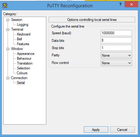
I didn't even consider using the standard Serial Monitor application built into the IDE and instead grabbed a copy of PuTTY and set the serial port up at 1000000 baud.


At this baud rate, the Arduino had no issues and PuTTY correctly decoded the serial stream without issue.  So, if 1M is good, then 2M should be twice as good, right?

Well, not exactly.  at 2,000,000 baud the per character rate is twice the rate, but the overall throughput actually dropped visibily.  By my crude measurements, the throughput dropped by about 15%.  But, it is good to know that Arduino can push serial bits out at a respectable speed.

One side effect to note is that the IDE must override the Serial baud rate in order to program the device.  When running at these very fast serial rates, it can be a bit hit and miss.  If you have trouble, press the reset button and release it just before the compile finishes and you will help it recover.  Another alternative would be to use an external ISP programmer.

Another thing to keep in mind is that the IDE and PuTTY are both going to try and use the same COM port.  The IDE will use it for programming the chip.  PuTTY will use it to monitor the serial output.  In order for the IDE to be able to program the chip, it must be able to open the serial port.  So, you will have to terminate PuTTY before attempting to reprogram the Arduino.

I have read a lot of complaints lately about trying to debug Arduino code with the serial port output.  While upping the serial speed will not help in situations where interrupts are disabled or where time required to output debug data adversely affects the running code, being able to output the data orders of magnitude faster is certainly going to help in general.  If you are doing a lot of edit, compile, flash, run cycles, it might be better to use an ISP programmer so that PuTTY or whatever serial terminal application you use can stay connected to the debug serial port.

In my work with faster embedded processors, 2-3M baud is about the limit even on these devices with much faster core and peripheral clocks.  The Freescale K60 for example is running at 96 MHz in my configuration and at 2M baud on the debug port, I still get data loss, but it is solid at 1M baud.  I think that for high speed output or where you need to output debug information during interrupt processing, it may be a better choice to use SPI for debug output to a dedicated device that can capture and save the output such as a PC with a USB/SPI interface or another Arduino that can write to a storage device such as an SD card.

Tuesday, August 18, 2015

Android Phone (Samsung Galaxy Note 4) Power Usage

I was playing around recently with my Android phone and decided to take a look at it's power consumption when charging from my laptop USB port.


While the device comes with a quick charge power adapter, my little USB power meter is not expecting to draw a couple amps from a USB circuit, so in the interest of not damaging it, I gave it a standard USB 2.x port as a power source.  As we can see it is quite hungry and draws a consistent 2.1 watts in this mode, with only about 75 mA headroom on a standard USB charging rate of 500 mA.  The device does not seem to change its power consumption when using the device while charging or allowing it to sleep.  The device uses the typical method of various sense resistor values between the USB pins to determine if the special charger is in use or a standard one to limit current draw to USB specifications.

When charging on the quick charger, I am seeing about 1.27 amps when measured with my multi-meter, but it seems to walk around a bit from about 1.0 to 1.45 amps.

Once the charger has brought the battery up to 100% charge, I put it back on my little USB power meter and find a much more respectable 43 mA current draw.  Again, it doesn't seem to matter if the display is lit or not.


Sunday, July 26, 2015

Controller check-out

I have FINALLY found my ISP programmer and been able to check out the postage stamp controller and made it to the typical embedded "Hello World" application of a blinking LED.


The small board in the upper left is an ESP8622 wifi module that is hanging out from a previous project.  I have flashed the ATMega328 part with the following typical example code:

void setup()
{
  pinMode(13, OUTPUT);
}

void loop() 
{
  digitalWrite(13, HIGH);
  delay(1000);
  digitalWrite(13, LOW);
  delay(1000);

}

The USBTinyISP programmer had no problem flashing the code to this part, but at initial blush, it appeared that nothing was working.  Then after a very long delay, I saw the LED turn on.  Reducing the delay values to 100 resulted in approximatly 1 second timing of the LED flashes.  So, it appears that the clock was not running at 16 MHz.

On a whim, I decided to flash the optiboot boot loader to the device and let the device reset and then erase the chip and reflash the test application above with no boot loader present.  This in fact fixed the problem.  

In looking at the datasheet, I see the following:


So, it appears that out of the box, a new ATMega328 is going to default to a 1 MHz system clock.  I will have to look at the optiboot code, but I am sure it is fiddling with the clock select bits which would explain the behavior I have seen.

In any event, I now have a tiny little microcontroller that needs no boot loader (saving that space in flash) and can be used for my projects that can use such a controller.  I have a couple updates that I need do to the PCB and will publish my updates on OSHPark where anyone can order the boards as desired.  $5 for 3 boards is a bargain.  More to the point is that I got something useful out of an attempt to learn a little more about KiCAD.

Saturday, July 18, 2015

Postage Stamp Micro-controller

In a previous post I described a little one inch square micro-controller based on the ATMega328 which I decided to build in order to learn KiCAD.  I have the boards back from OshPark.


To my way of thinking, it is a pretty good bargain to be able to obtain this lot of boards for the grand total of $10 plus shipping.  In any event, I have built up one of the units as seen below.


I have a couple of errors I will need to fix.  The first is that the row of header pins on the left and right side are not quite on 0.1 inch centers.  I plugged the headers into a prototype board while soldering and they both bend towards the centre of the board, so I need to space them a little closer together.  Oops...  The top and bottom headers are mounted on the top side of the board to allow plugging the board into a prototype board and still having all pins available.  I would expect to typically hard-wire the board into whatever circuit it will be employed in and then mount it down with double sided tape.  This one however is for bread-boarding.

The second error is that I used the wrong footprint for the thru-hole crystals that I have on hand and so it cannot sit completely down on the board.  Oh sigh...  Easy enough to fix however and I will make those updates before I publish the board at OshPark.com.

The ATMega328 chips are raw ones with no boot loader, so I will have to program them with the ISP header.  This can be done with another Arduino or any of the ISP programmers such as the USBTinyISP.  No boot loader is required on this device as there is no USB or other programming interface other than the ISP connector so therefore the entire flash is available for your code.


Thursday, July 2, 2015

KiCAD

Since being laid off at Dynon Avionics, I have been looking around at schematic capture and PCB CAD packages.  Chris at Contextual Electronics has encouraged me to try out KiCAD.  I decided to give it a go and design a small 1 square inch microcontroller board with a full-on ATMega 328 processor and the minimum circuitry necessary to build an (almost) UNO clone.  The "almost" part is the fact that there will be no USB port on the board and it will need be programmed using the ISP connector.

The circuit diagramme I decided on looks like this from KiCAD:


Nothing here that doesn't need to be here for a minimal controller.  I have the entire I/O pin set that can be found on an UNO, plus since I use the TQFP package, I have two additional analogue input pins.

The board layout is pretty dense at one inch square.  Here is the board layout showing all of the layers from KiCAD.  I am not terribly impressed with KiCAD's copper pour capabilities, at least as far as I have explored them, but what do you want for free, eh?


Producing the Gerber files was trivial and I zipped up the lot of them and shipped them off to OSHPark to be manufactured.  Here is the screen shot of their rendering of the gerber files for the front and back of the board.


So, now we wait for the little purple envelope to arrive.  Meanwhile I will collect up the set of parts to build a few of these up.  This was an experiment to enable me to learn KiCAD and at the same time to produce a useful gadget for other projects.  Once I have verified the functionality is correct, I will publish the OSHPark boards so others can order them directly if desired.  At $5 for 3 of them, they are pretty cheap.

Overall, I found KiCAD relatively easy to learn, once I got a couple of key concepts down.  The main one was that hot keys apply to whatever your mouse is hovering over.  I found myself wanting to click to select something before hitting a hot key and this lead to all sorts of grief.  Moving objects once they are placed also needs a lot of work.  Rubber-banding of traces pretty much sucks.  Once I figured out how to drag an object, the best that KiCAD could do is straight line connect all the existing traces.  This ends up being pretty much worthless for anything other than adjustments of a few centimetres and you end up deleting all the traces and redrawing them anyway.

Selection of wires in schematics needs an easy way to select only a line segment or the entire line without having to draw box around it.  When you move the line, it needs to rubber-band the end points.  Straightening out a series of segments needs to collapse them into one segment and it needs to be able to easily break a line segment in two without disconnecting them.  All of these comments also apply to traces in the PCB layout editor.

I did like that KiCAD included the ability to view gerber files, a comprehensive footprint editor as well as building the notion of hierarchical schematics into the product as a key feature.  I cannot however get the bill of materials functionality to work, so I must be doing something wrong.  Always more to learn. 

For a free, open-source product, it is quite compehensive and there are a lot of part footprints available out-of-box and from 3rd parties.  Overall, I would continue to use it for hobby projects.  I would need to try and build at least a four layer board to have an opinion about suitability for commercial projects.

Thursday, June 25, 2015

Change of status

Today I accepted a Firmware Engineer position with LOUD Technologies in Woodinville, WA working with the Mackie Digital Audio Mixing team.  I will be starting mid-July, so my job hunt status appears to be over.  Yay!  Check out their web site when you get a chance.  http://loudtechinc.com/

Wednesday, June 3, 2015

Diode Ring Mixer - UPDATED

In an attempt to firstly melt more solder than I have of late, and secondly to try and actually understand the operation of a mixer, I have decided to build one up from discrete components, including (gasp) winding my own transformers.

The rather rough diagramme of the circuit I propose to build looks something like this which is based on the fine design by Pete Juliano N6QW found here:


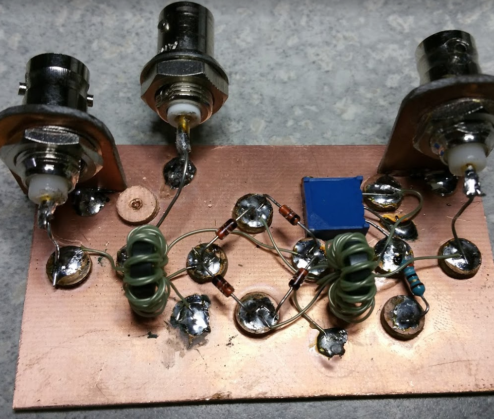
I found a few 1N6263 Schottky diodes in my junk box and out of the lot was able to find four that matched on the forward voltage drop to the millivolt level at 0V300.  A quick look around found a bit of PCB and a 1/4 inch sheet metal hole punch allowed me to create simple Manhattan pads.  Here is the layout at the start of the build with just the diodes installed.


I wound coils on FT37-43 cores.  I seem to be out of enameled wire, so I am going to try this with 30 gauge insulated wire-wrap wire as the number of turns is small, though the coils are trifilar.  I wound the trfilar wires together using a drill motor and then wound the three wires onto the core.  Ten turns, both coils are identical.


Separating the coil winding ends, I check continuity on them and mark them with a Sharpie (why is a dull felt pen called a Sharpie?) on each end of the wire with no mark, a single mark or a double mark.  The no mark wire will be the single coil while the one and two mark wires will be hooked in series (observing phasing).  The left side as drawn in the circuit above, will have a 100 ohm variable resistor at the centre tap of the transformer secondary to allow small balance adjustments.  As suggested by Pete Juliano N6QW, but not drawn above, I plan to also include a 39 ohm resistor that is switchable to ground from the centre tap in order to intentionally unbalance the mixer.  This is useful for injecting carrier for tune-up purposes for example.

The final build, minus the output filter can be seen below.  I hope to get out of interview preparation mode soon so that I can have some time to check this out.  The trim pot is a 100 ohm multi-turn pot to allow fine tuning of the balance.  Connecting the top of the 39 ohm resistor to ground will deliberately unbalance the mixer.


Finally got a chance to see if this little guy is mixing or not.  I set the 100 ohm multi-turn pot to the middle and attached the output of a 20 MHz crystal oscillator to it along with a signal generator output and had a look at the output on the spectrum analyzer.  Firstly, we needed some connectors.


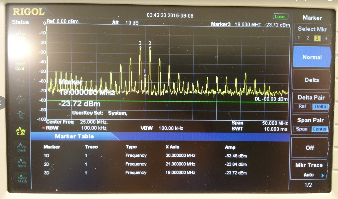
I gave it 20 MHz on one port, 1 MHz on the other, both at 7 dBm and obtained the following output.  Both the sum and difference were within 0.08 dBm of each other.


So, we seem to be mixing and with proper IF filtering following, should be good to go.  Many thanks to Wayne NB6M for helping with the testing.