As previously mentioned, I held two possible interpretations of the datasheet regarding what is meant by how far the DCO frequency could be moved without restarting it. My initial belief was that as long as no single change was more than 3500 ppm plus or minus that you could move it over the entire DCO range. This turns out to be false. You re-establish what the datasheet calls the "centre frequency" when you recalculate the RFREQ, HSDIV and N1 values and set them to the device. A closer examination of the datasheet revealed the following:
As shown in Figure 3, the device allows reprogramming
of the DCO frequency up to ±3500 ppm from the center
frequency configuration without interruption to the
output clock. Changes greater than the ±3500 ppm
window will cause the device to recalibrate its internal
tuning circuitry, forcing the output clock to momentarily
stop and start at any arbitrary point during a clock cycle.
This re-calibration process establishes a new center
frequency and can take up to 10 ms. Circuitry receiving
a clock from the Si57x device that is sensitive to glitches
or runt pulses may have to be reset once the
recalibration process is complete.
So, it is in fact this recalibration process that establishes the new centre frequency. This has been verified by experimentation.
From this I conclude there is a small frequency change procedure and a large frequency change procedure. If the DCO frequency is changed no more than +/- 3500 ppm from the last centre frequency the a simple ratio multiplier is applied according to the following formulae:
Once a new RFREQ value (38 bits) is calculated, it is written to the Si570 device. Since several registers must be rewritten, even with tiny changes in the RFREQ value these changes can affect the DCO frequency while the set of registers are being updated. The Si570 provides a bit (register 135 bit 5) that can prevent this behaviour. Setting this bit to 1 before changing the RFREQ registers and then resetting it will allow the output frequency to change in a single phase continuous step to the new frequency.
When changing the DCO frequency by more than +/- 3500 ppm, several steps are involved. Firstly, new values must be calculated for the HSDIV and N1 divisors. Given the new desired output frequency, you must find the frequency divider values that will keep the DCO oscillation frequency in the range of 4.85 to 5.67 GHz.
To help minimize the device's power consumption, the divider values should be selected to keep the DCO's oscillation frequency as low as possible. The lowest value of N1 with the highest value of HS_DIV also results in the best power savings. Since there are many solutions for a given output frequency, it is useful for power sensitive applications to pay attention to these details.
Once the divisors have been calculated, a new RFREQ value is determined according to the following formulae:
The new values are written to the device as follows:
- Freeze the DCO by setting bit 4 of Register 137
- Write the new frequency configuration by setting RFREQ, HSDIV and N1 new values to the appropriate registers.
- Unfreeze the DCO and assert the NewFreq bit without exceeding the timeout specified in Table 11 of the Si570 datasheet. (Register 135, bit 6).
The DCO output clock will momentarily stop and start at a completely arbitrary point in the clock cycle and can take up to 10 ms to complete with the expected assortment of glitches and runt pulses such behaviour would indicate. If your downstream circuitry is sensitive to this nonsense, you may need to provide a reset mechanism to recover.
I find that the output waveform is basically a square wave signal. On my device at least there is a bit of overshoot on the square wave signal both positive and negative at least at lower frequencies. As I go higher in frequency, the waveform becomes more triangular in shape. I will post oscilloscope traces of this behaviour later as my scope is a bit tied up right at the moment with another project.
More to come...
The relationship between the various frequency setting elements is described as follows:
As previously mentioned, the output frequency is the result of the DCO frequency divided by the product of two divisors. The DCO frequency is the product of a crystal frequency in the 114.25 MHz range and a settable reference frequency and must remain within the range of 4.85 to 5.67 Ghz. RFREQ has 38 bits of resolution allowing for a theoretical frequency setting resolution of 0.09 ppb at the test frequency of 114.285 MHz.
The HSDIV and N1 values have additional restrictions on them, specifically HSDIV can have the values 4, 5, 6, 7, 9 or 11. N1 can be 1 or any even number up to 128 inclusive (1, 2, 4, 6, ... 128).
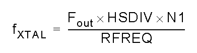
Typically at startup you would determine the fxtal value specifically for your chip:
By interrogating the chip, one can determine the values for HSDIV, N1 and RFREQ. By knowing the default startup frequency, the crystal frequency can be calculated. In my case, HSDIV = 11, N1 = 8 and RFREQ is 0x2B6109f08. Dividing this value by 2^28 gives me 0x2b as the integer portion or 43 decimal. To figure out the fractional part one would divide 0x6109f08 (the least significant 28 bits of RFREQ) by 2^28. Working in decimal instead of hex:
0x6109f08 = 101752584 / 2^28 = 0.3790579140
Adding this to the integer portion gives me a RFREQ value of 43.3790579140. Plugging this and the other knowns into the formula above gives me:
fxtal = (56320000 * 11 * 8) / 43.3790579140 = 114252365.964832 or 114.252365 Mhz
The datasheet states that the crystal frequency is only accurate to +/- 2000 ppm at 114.285 Mhz, or about +/- 0.22857 so my device is within the pretty horrible specification.
So, running this the other way, the output frequency is found as:
fout = (114252365 * 43.3790579140) / 11 * 8 = 56319999.524391 = 56.32 Mhz
A guy could envision a mechanism wherein you output a WWV frequency and tweak RFREQ until zero beat and then store the value for future reference, but the known frequency technique will get you very close.
If the DCO frequency is only moved +/- 3500 ppm, the oscillator output will be phase continuous. This should make implementing protocols such as WSPR, JT65 and the like much cleaner than my previous work using the Parallax Propeller. Also, in theory there is .42 Hz frequency resolution capable which would allow for much closer FSK tone shifts used in WSPR than the 1Hz resolution I had with the propeller.
It is unclear from the datasheet what is precisely meant by the +/- 3500 ppm figure. One interpretation is that once you have moved a total of 3500 ppm from whatever frequency you last set using the "large frequency change technique", you would have to recalculate the RFREQ and divisor values and set them back to the device. In my experience, most of the Arduino implementations I have reviewed have taken a flavor of this approach. While this is certainly safe, it is unlikely to be necessary. The other interpretation I have of the datasheet is that you could move the DCO over its entire range without recalculating parameters and do it in a phase continuous manner as long as no single frequency change is more than 3500 ppm. My interpretation is that once you have changed the frequency by either of these mechanisms, the new DCO frequency (not the output frequency) becomes the new "center frequency" described in the datasheet. So, under my theory, you could move the output frequency a total of 5.67 - 4.85 GHz = 0.82 Ghz 3500 ppm at a time. Of course, this would require a different part than I have which only has a range of 10-160 Mhz. Under this theory, as long as you didn't jump more than 17.5 Mhz between frequency settings, you only have to recalculate RFREQ and the change in frequency could be done phase continuous. This theory I have not yet tested.
More to come...
Messing around with the Si570 chip that is used in the Minima transceiver designed by Farhan Akhtar. This is my lash-up:
After a bit of tweaking, I have the oscillator working. It is no picnic trying to interpret the Si570 datasheet however.
Interestingly enough most of the code implementations I have looked at for the Arduino make a couple of errors in interpretation of the datasheet. The Si570 is not really fun to program, but it has a number of benefits going for it.
My particular chip is a 10-160 MHz CMOS model. When I first power it up, it comes up at 56.320 MHz. The datasheet is not explicit on this, but supposedly the individual parts are "tuned" at the factory to their default frequency by adjusting the various parameters that are used to set the frequency. However, the datasheet does not provide very flattering stability numbers and nowhere does it provide a statement of how closely it is calibrated in the factory.
So, in the absence of highly accurate frequency measurement capabilities you are faced with having to calculate the internal crystal frequency based on the default output frequency (from the datasheet) after reading the frequency setting parameters from the chip itself.
The Si570 requires mathematical calculations with 38 bits of precision in order to accurately set it's frequency. Most Arduino implementations rely on double precision floating point math functionality. However, the Arduino implementation of double precision is in fact identical to its single precision floating point. Namely double = float data types silently behind the scenes. So, most of these implementations give up on the number of digits of precision required to control the Si570 even down to the 1 Hz level. Theoretically you should be able to set the frequency to within .42 Hz, but the unfortunate floating point double precision implementation on Arduino prevents even 1 Hz resolution.
The Si570 stores a reference frequency used in the output frequency calculation as a 38 bit values where 10 bits are use as a decimal multiplier. The remaining 28 bits are a fractional multiplier stored as an integer value scaled by 2^28.
The internal DCO is constrained to 4.85 to 5.67 GHz determined by the internal crystal frequency multiplied by a reference frequency. According to the settings in my chip, I calculate my crystal frequency to be 114.252365 MHz. Secondarily, frequency excursions of the DCO can be done in a phase continuous manner if the change in frequency is no more than +/- 3500 PPM. Many implementations however are calculating this based on the output frequency rather than the DCO frequency in error. Frequency excursions larger than this require the DCO to be stopped and restarted in a non-phase continuous manner that can take upwards of 10 ms to complete. Circuitry sensitive to runt pulses may require resetting after this operation.
The output frequency is the DCO frequency divided by the product of two divisors. There are additional restrictions on these two divisors.
More to follow...