Well, I obtained a nice temperature compensated 10 MHz clock for my propeller board, courtesy of Eldon WA0UWH. Here you can see the little daughter board that Eldon designed. The normal 5 Mhz crystal has been removed and the software adjusted to set the system clock at times 8 instead of times 16, so we are still running at 80 MHz.
After spotting it on 10.140.200 MHz I captured my WSPR decode and as you can see in the last spot after touching up the pot a little, I am spot on frequency (10.140.200) and zero drift. Yeah! The waterfall display shows me swinging the pot through its range over several samples.
The board has a nice, though a little touchy pot to net the frequency where you want it. It currently has a range of about 100 Hz. In the final version, I think this will be tweaked to slow the tuning down to about 1/2 that amout or so. Once adjusted it stays put and doesn't seem to be affected by temperature as expected.
The oscillator output looks like this:
So, I am quite pleased with this little modification to the propeller proto board.
I decided to measure the propeller RF oscillator accuracy tonight. I find that my random sample of one Propeller Board to be accurate to 1 ppm over the range of 1 Mhz to 100 Mhz. In my case, the error is always negative requiring a positive offset to correct back to the proper frequency.
From this, I should be able to calculate an error offset for the oscillator over the entire frequency range once the error correction at any given frequency is known for the particular propeller board.
Drift on this particular board at 10 Mhz appears to be around 2 Hz over 2 minutes time, which represents a typical WSPR transmission. My next set of experiments with drift control will be to temperature stabilize the propeller chip at about 50 degrees C and see how this affects drift.
I have been running my Propeller WSPR beacon over night and have gathered 42 data reporting points on drift and frequency as reported by WSPR 2.11 over a 7 hour period. The beacon is transmitting every 10 minutes and idle between times. The only temperature control is to wrap the device in foam.
The charts below are are showing the frequency reported by WSPR 2.11, which as I understand it will be the first frequency it decodes and the amout of drift from that frequency over the life of the transmission.
There are a few somewhat wild excursions initially, but then over time the initial frequency appears to drift upwards with each successive 10 minute period as the device cools.
The amount of drift once the transmission begins is in the opposite direction and after some initial jitter assumes asymptotic behavior at a consistent 2 hertz downward drift as the device warms up.
While none of these figures is horrific, good engineering would indicate that for this kind of application, careful attention to thermal stability is important.
After wrapping the propeller board in foam, from a cold start, after about 30 minutes the frequency stabilized at about 30 Hz lower than the cold start value.
So, it appears that my chasing of this error correction value has been a bit of a boondoggle as I had not attended to the temperature stability of the device. (Doh!) I should be able to zero in on my ErrorOffset value and be able to let it be, or so I hope.
This evening, I have been experimenting a bit with my Propeller device. I have a small script that turns on the RF synthesizer at 10_140_000 mHz for 30 seconds, off for 10 seconds etc. I use it for calibration of the frequency of the board in use as different Propeller boards will have different amounts of error in frequency generation. The script looks like this:
CON
_CLKMODE = XTAL1 + PLL16X
_XINFREQ = 5_000_000
CLK_FREQ = ((_CLKMODE-XTAL1)>>6)*_XINFREQ
MS_001 = CLK_FREQ / 1_000
RFPin = 27
TxFreq = 10_140_000
ErrorOffset = -467
Frequency = TxFreq + ErrorOffset
VAR
OBJ
Freq : "Synth"
PUB Main
repeat
sendTone(0)
delay(30000)
noTone
delay(10000)
PUB delay(ms) | t
t := cnt - 1088 ' 1088 is published time for overhead
repeat ms
waitcnt(t += MS_001)
PUB sendTone(tone)
Freq.Synth("A",RFPin, Frequency + tone)
PUB noTone
Freq.Synth("A",RFPin, 0)
This simple little script I find to be very useful when I need to generate a signal at some frequency. The on/off modulation of the signal allows me to find it more easily on uncalibrated receivers.
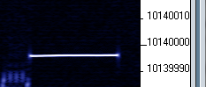
Viewing the output from a local receiver using Argo we find this waveform. As you can see, my board has approximately -467 Hz of error which is corrected for in this script. Nevertheless, as the board changes temperature, it does drift a bit. As can be seen below I have drifted a hertz or two lower since calibration of the board was last done.
I begin to wonder however why this ErrorOffset value seems to change when using the same board, just a different application. For example my Hellscrieber code appears to transmit about 3 Hz lower with the same ErrorOffset value. I added a 30 second carrier at the beginning of the code to see exactly what frequency it is on before launching into the transmission of FeldHell codes. With the transmit frequency set to 10_139_980 and the same -467 ErrorOffset value, the following is observed:
I am clearly 5-6 Hz low. The frequency is also different than in the previous example, so that may be related. I think however that it may just be the drift of the device. Going back to the Tune application, which should be a hertz or two low at 10_140_000, we see the following:
Hmmm... So it appears that I am just chasing a temperature drift of the Propeller board over time. Adding some thermal stabilization to it would probably help. I will wrap it up in some foam and let it run for a while and see if the frequency stabilizes.
Here is a cold start image of my QRSS signal. Out of the box, it seems that there is a significant drift:
And a few minutes later we can see it has drifted over 20 Hz:
I will let it run and see where it stabilizes.